Quantcast
Channel: GameDev.net
Viewing all 17625 articles
Browse latest View live

Which is Most Verbose: OpenGL or DirectX?

$
0
0
Direct3D and OpenGL are competing application programming interfaces (APIs) which can be used in applications to render 2D and 3D computer graphics. They are the two most popular graphics APIs utilized in game development.

Probably the most recurrent debate between the two APIs has to do with their relative performances, which concern more the end user. In this post we will discuss their verbosity, which impacts more the developers using them.

Comparing the DirectX and OpenGL


To compare the verbosity of the two APIs, let’s analyse with CppDepend the Irrlicht 3D engine source code which implements both DirectX and OpenGL renders.

The Irrlicht Engine is an open-source high-performance realtime 3D engine written in C++. It is completely cross-platform, using D3D, OpenGL and its own software renderers. The Irrlicht rendering logic is implemented in the irr::video namespace, and the base interface for material rendering is
irr::video::IMaterialRender.

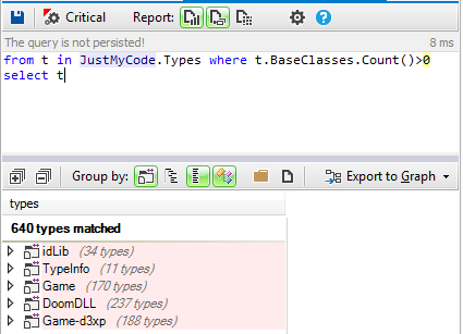
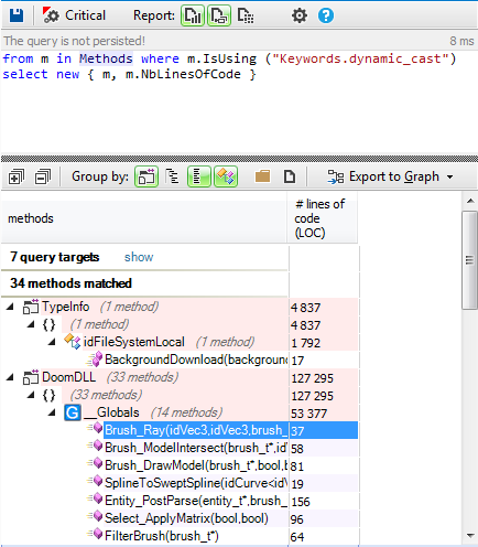
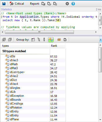
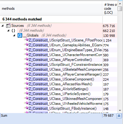
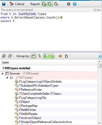
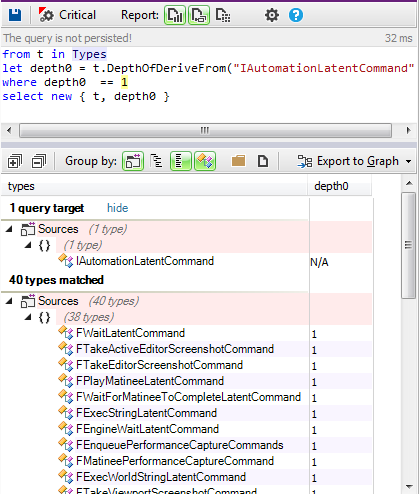
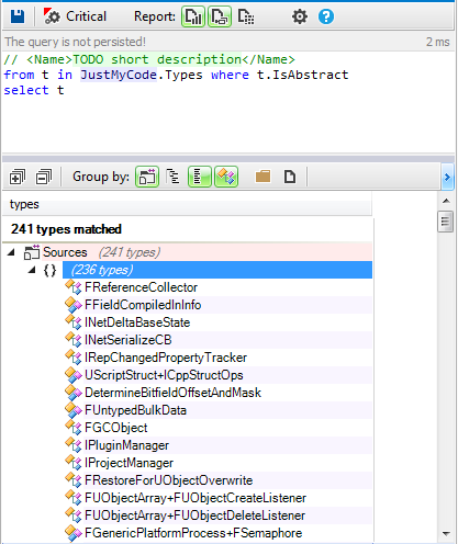
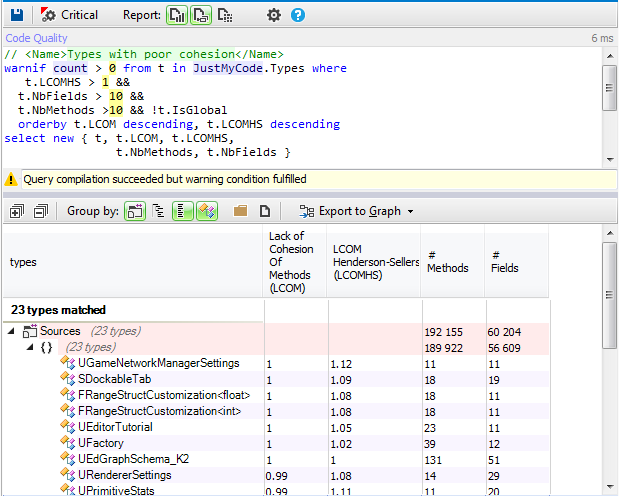
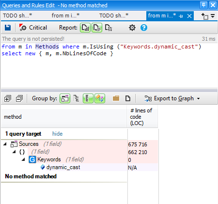
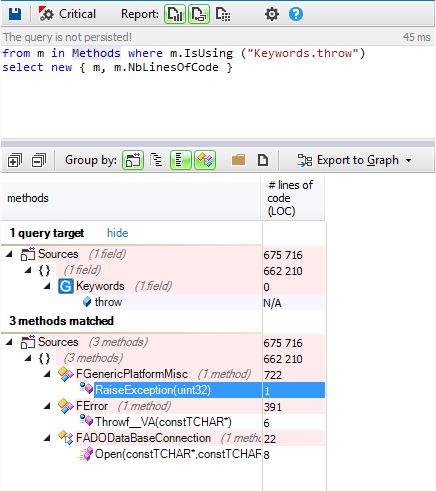
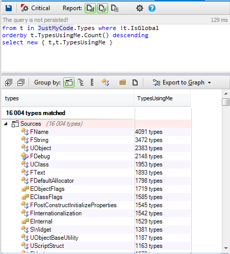
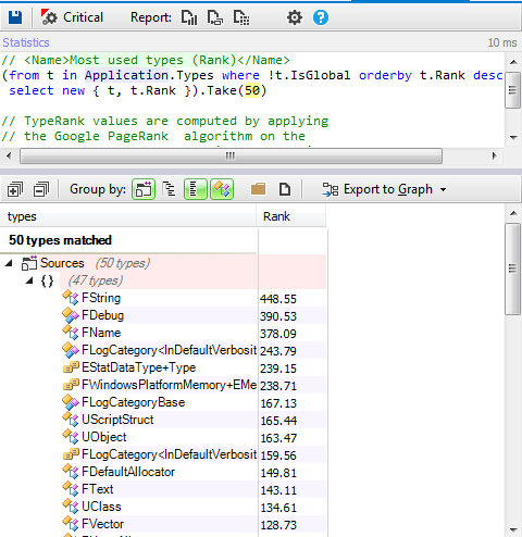
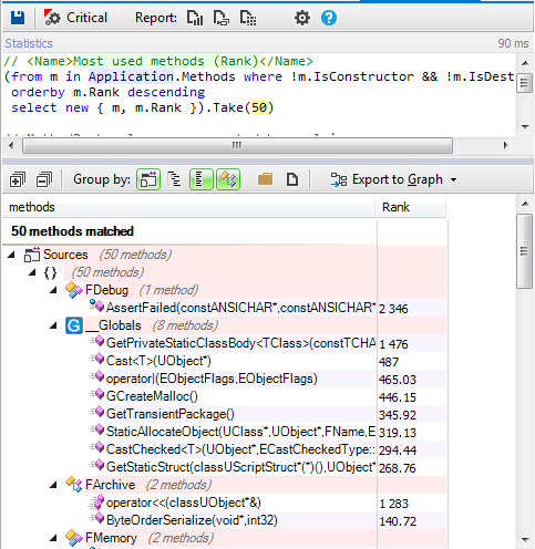
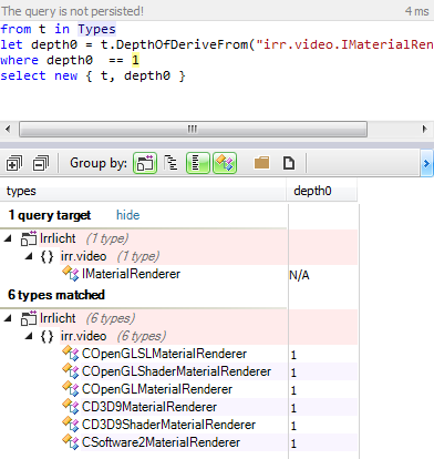
Let’s search for all the classes implementing directly the irr::video::IMaterialRender interface.

Attached Image: irrelicht8.png

Both DirectX and OpnGL renders are implemented. the COpenGLSLMaterialRenderer, COpenGLShaderMaterialRenderer, CD3D9ShaderMaterialRenderer and CD3D9MaterialRenderer are the base classes for all the other rendering classes.

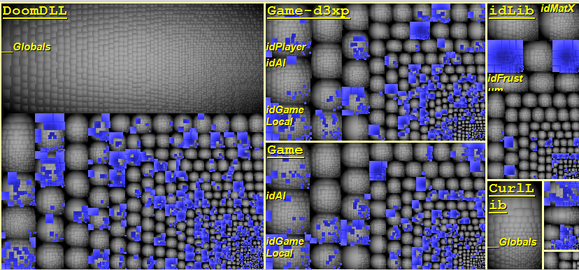
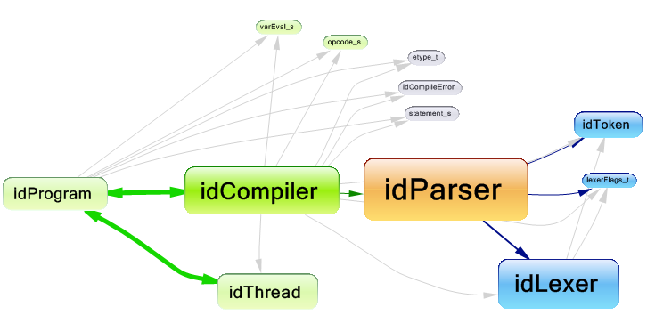
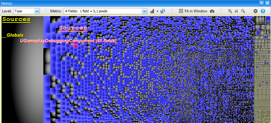
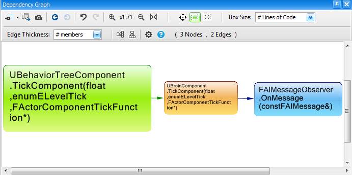
Let's export the result of the previous query to the dependency graph:

Attached Image: irrelicht2.png

In this graph the rectangle size is proportionel to the size of code, and as we can observe the OpenGL rendering base classes are bigger than the DirectX ones.

The fact that the OpenGL base classes are bigger does not mean that the OpenGL implementation is more verbose, but it could mean that the OpenGL rendering implementation has more common rendering code than DirectX. therefore we have to compare the implementation of all the renders inheriting from these base classes.

OpenGL renders

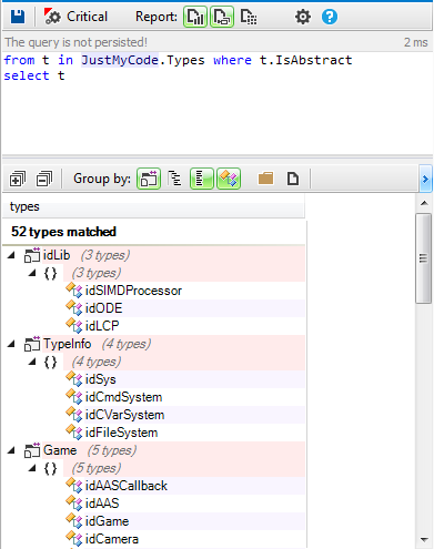
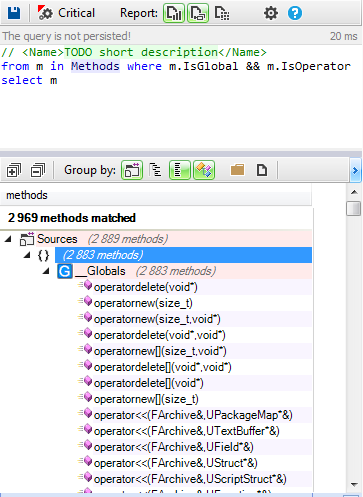
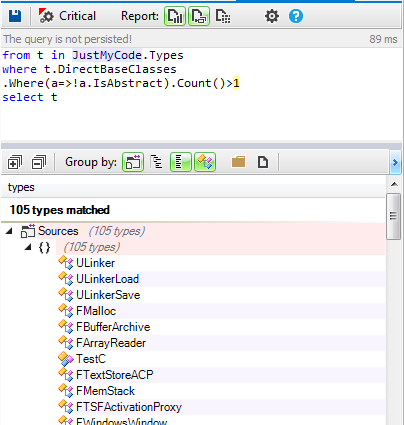
Let's search for all classes inheriting from COpenGLSLMaterialRenderer and COpenGLShaderMaterialRenderer directly or indirectly:

Attached Image: irrelicht3.png

The OpenGL renders implementation has 548 lines of code.

DirectX renders

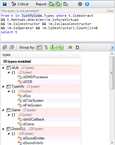
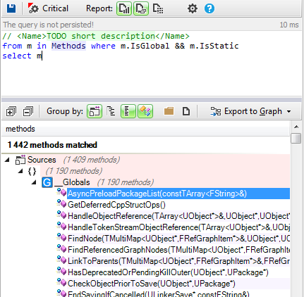
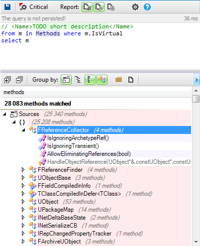
Let's search for all classes inheriting from CD3D9ShaderMaterialRenderer and CD3D9MaterialRenderer directly or indirectly:

Attached Image: irrelicht4.png

The DirectX renders implementation has 296 lines of code.

Like the rendering base classes, the sum of the OpenGL implementation rendering classes is more than the DirectX ones.

To investigate more this difference let’s compare the implementation of the method OnSetMaterial in COpenGLMaterialRenderer_SOLID and CD3D9MaterialRenderer_SOLID classes:

DirectX implementation

virtual void OnSetMaterial(const SMaterial& material, const SMaterial& lastMaterial,
bool resetAllRenderstates, IMaterialRendererServices* services) _IRR_OVERRIDE_
{
  services->setBasicRenderStates(material, lastMaterial, resetAllRenderstates);

  if (material.MaterialType != lastMaterial.MaterialType || resetAllRenderstates)
  {
    setTextureColorStage(pID3DDevice, 0,
    D3DTA_TEXTURE, D3DTOP_MODULATE, D3DTA_DIFFUSE);
  }

  pID3DDevice->SetTextureStageState(1, D3DTSS_COLOROP, D3DTOP_DISABLE);
}

OpenGL implementation

virtual void OnSetMaterial(const SMaterial& material, const SMaterial& lastMaterial,
bool resetAllRenderstates, IMaterialRendererServices* services) _IRR_OVERRIDE_
{
  if (Driver->getFixedPipelineState() == COpenGLDriver::EOFPS_DISABLE)
    Driver->setFixedPipelineState(COpenGLDriver::EOFPS_DISABLE_TO_ENABLE);
  else
    Driver->setFixedPipelineState(COpenGLDriver::EOFPS_ENABLE);

  Driver->disableTextures(1);
  Driver->setBasicRenderStates(material, lastMaterial, resetAllRenderstates);
  
  if (resetAllRenderstates || (material.MaterialType != lastMaterial.MaterialType))
  {
    // thanks to Murphy, the following line removed some
    // bugs with several OpenGL implementations.
    glTexEnvi(GL_TEXTURE_ENV, GL_TEXTURE_ENV_MODE, GL_MODULATE);
  }
}

As we can observe, the logic of setting basic states for DirectX is centralized in one method, however for OpenGL we need 6 lines of code. But this difference could be due to the developers implementation choice. And maybe the setBasicRenderStates of Directx include the lines added in the OpenGL implementation.

Let's search for all setBasicRenderStates methods:

Attached Image: irrelicht7.png

The COpenGLDriver::setBasicRenderStates method is more bigger than CD3D9Driver::setBasicRenderStates. which makes the OpenGL implementation more verbose.

Number of calls needed to the OpenGL and DirectX APIs


Another more reliable indicator to check the verbosity concerns the number of calls to the external API library needed to do some treatments.

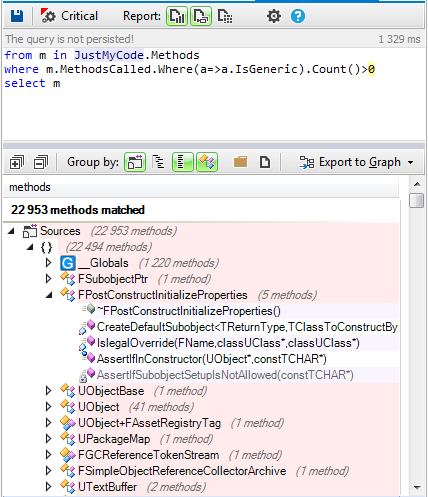
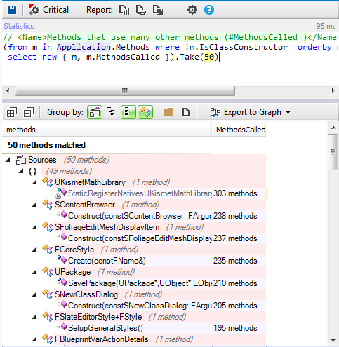
Let’s take as example the big classes irr::video::COpenGLDriver and irr::video::CD3D9Driver from the rendering logic and check how many calls they need.

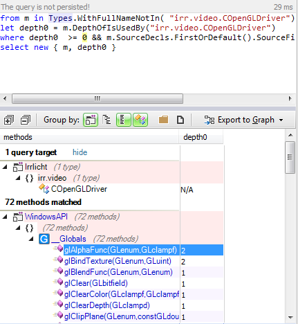
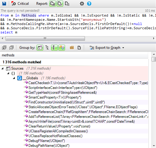
Let's search for all the OpenGL functions called directly or indirectly from the COpenGLDriver class:

Attached Image: irrelicht5.png

The OpenGL driver needs 72 calls to the OpenGL API.

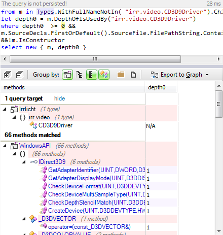
And concerning the CD3D9Driver class:

Attached Image: irrelicht6.png

The DirectX driver needs 66 calls to the DirectX API.

Conclusion


When searching the web for which of the two APIs is more verbose, more developers say that DirectX is the most verbose one, however it's not necessarily true, it depends more on the the developer's design and implemenation choices.

For example, in this case of the Irrlicht engine, the OpenGL implementation is more verbose than the DirectX one, and it could just as well be the inverse for other game engines.

T4 Code Generation in Unity

$
0
0
Many Unity APIs use a string identifier, such as the game object’s tag for various things (e.g: checking for a collision with “player”). In this article I explore a different, safer and automated technique that achieves the same result, without using strings.

The String Problem


Consider the following code:

var player = GameObject.FindWithTag("Player");

The code is not type safe: it relies on a string identifier to perform an object lookup. This identifier may change, making this code “out of sync” with the project, or be misspelled, making the code fail. In addition, this string might be used in many different locations of the code, increasing the risk of previous mentioned concerns.

A Solution “Sketch”


A possible solution to this issue is to create a static helper class that will expose all tags as public (static) fields. When needed, instead of using a string, we’d use the class’s static fields:

public static class Tags
{
    public static readonly string Player = "Player";
}

Accessing this tag is safer now, since we’re not (directly) relying on the string representation of the tag:

var player = GameObject.FindWithTag(Tags.Player);

Effectively, the code will operate the same as before, but now we have a single location where the tag is declared.

There are 2 main issues with this approach:

  1. In case there are many tags defined in the project, creating the helper class can be a somewhat tedious task (creating a field per tag).
  2. In case a tag’s name changes in the Unity editor, you have to also remember to replace its corresponding value in the helper class.

It seems that this solution is a step in the right direction, but we need some extra “magic” to make it perfect.

Code Generation To The Rescue


Code generation is an (oftentimes) overlooked practice, where code is being automatically generated by some other code, a template or some tool. In particular, code generation really shines in cases where we want to generate long, repetitive code from an underlying data source.

Translating this to the problem described above, we would like to generate a static helper class with many static fields from an underlying data source (a collection with all of the project’s tags).


Attached Image: 46974122-300x271.jpg


To achieve this, we’ll use one particular implementation of a code generation engine called T4, which is a template engine that comes with Visual Studio (which also heavily relies on it for various tasks), and also comes out of the box with Mono (yes, the same one that is installed with Unity).

A T4 template is a file (with a .tt extension) that mixes a body of text with special directives. The template generates a single output file (usually, a code file, although it can generate any other file format).

T4 Templates


In order to add a T4 template to your project, right click on your code project in MonoDevelop, and select: Add->New File. T4 Templates can be found under Text Templating on the left:


Attached Image: t41.png


T4 Template Types


There are 2 types of available templates (ignore Razor templates as they’re irrelevant for this discussion):
  • T4 Template – a template file that gets transformed during compilation time into the output file. This type of template is used to generate code files that are needed at design time (e.g: think of Microsoft’s Entity Framework, where a set of classes can be generated at design time from a database, instead of being created manually by the developer).
  • Preprocessed T4 Template – a template file that creates an “intermediate” class that can later be used to generate the output code file.

Unity Bug


Unity currently does not support adding T4 templates (.tt files) to scripting code – after compilation, all .tt files will be dropped from the code project (I reported this bug here.

This forces us to use option #2 – creating a one-time “intermediate” class. This class will be used by a Unity edior extension, from which we can generate the class we want and add it to the project.

Show Me the Code!


Here is the preprocessed T4 template that will generate the Tags class for us (although the provided sample uses the same template to generate a Layers class in exactly the same manner):


Attached Image: t4_example.png


A few things that should be noted:

  1. Any text not contained within <# #> tags is being output as is.
  2. The template is a preprocessed template. This means it does not generate an output code file directly. Instead, it generates an intermediate (partial) class with a TransformText() method that returns the template final output (the text with the generated class).
  3. The code prints out a header (the class declaration with some comments), then it iterates all elements in source and outputs a public static read-only field for each item (does a small manipulation to make sure the field name does not have spaces in it).
  4. The variables classname, item and source are actually implemented in a code file (a partial class with the same name as the template class. Remember I said the template generates a partial class? this allows mixing the template with some custom code. For more clarity, see the full code in the link below).

In Conclusion


This article aimed to open a hatch to the wonderful world of code generation (and T4 in specific), while showing how it can solve real world problems in a short and simple way. I did not dive into T4 syntax or more advanced topics (leaving it for you to explore, or as a subject for future articles). For more information regarding T4 – see the links below.

Links

How to Create a Scoreboard for Lives, Time, and Points in HTML5 with WiMi5

$
0
0
This tutorial gives a step-by-step explanation on how to create a scoreboard that shows the number of lives, the time, or the points obtained in a video game.

To give this tutorial some context, we’re going to use the example project StunPig in which all the applications described in this tutorial can be seen. This project can be cloned from the WiMi5 Dashboard.

image07.png

We require two graphic elements to visualize the values of the scoreboards, a “Lives” Sprite which represents the number of lives, and as many Font and Letter Sprites as needed to represent the value of the digit to be shown in each case. The “Lives” Sprite is one with four animations or image states that are linked to each one of the four numerical values for the value of the level of lives.


image01.png image27.png


The Font or Letter Sprite, a Sprite with 11 animations or image states which are linked to each of the ten values of the numbers 0-9, as well as an extra one for the colon (:).


image16.png image10.png


Example 1. How to create a lives scoreboard


To manage the lives, we’ll need a numeric value for them, which in our example is a number between 0 and 3 inclusive, and its graphic representation in our case is the three orange-colored stars which change to white as lives are lost, until all of them are white when the number of lives is 0.


image12.png


To do this, in the Scene Editor, we must create the instance of the sprite used for the stars. In our case, we’ll call them “Lives”. To manipulate it, we’ll have a Script (“lifeLevelControl”) with two inputs (“start” and “reduce”), and two outputs (“alive” and “death”).


image13.png


The “start” input initializes the lives by assigning them a numeric value of 3 and displaying the three orange stars. The “reduce” input lowers the numeric value of lives by one and displays the corresponding stars. As a consequence of triggering this input, one of the two outputs is activated. The “alive” output is activated if, after the reduction, the number of lives is greater than 0. The “death” output is activated when, after the reduction, the number of lives equals 0.

Inside the Script, we do everything necessary to change the value of lives, displaying the Sprite in relation to the number of lives, triggering the correct output in function of the number of lives, and in our example, also playing a negative fail sound when the number of lives goes down..

In our “lifeLevelControl” Script, we have a “currentLifeLevel” parameter which contains the number of lives, and a parameter which contains the “Lives” Sprite, which is the element on the screen which represents the lives. This Sprite has four animations of states, “0”, “1”, “2”, and “3”.


image14.png


The “start” input connector activates the ActionOnParam “copy” blackbox which assigns the value of 3 to the “currentLifeLevel” parameter and, once that’s done, it activates the “setAnimation” ActionOnParam blackbox which displays the “3” animation Sprite.

The “reduce” input connector activates the “-” ActionOnParam blackbox which subtracts from the “currentLifeLevel” parameter the value of 1. Once that’s done, it first activates the “setAnimation” ActionOnParam blackbox which displays the animation or state corresponding to the value of the “CurrentLifeLevel” parameter and secondly, it activates the “greaterThan” Compare blackbox, which activates the “alive” connector if the value of the “currentLifeLevel” parameter is greater than 0, or the “death” connector should the value be equal to or less than 0.

Example 2. How to create a time scoreboard or chronometer


In order to manage time, we’ll have as a base a numerical time value that will run in thousandths of a second in the round and a graphic element to display it. This graphic element will be 5 instances of a Sprite that will have 10 animations or states, which will be the numbers from 0-9.


image10.png

image20.png


In our case, we’ll display the time in seconds and thousandths of a second as you can see in the image, counting down; so the time will go from the total time at the start and decrease until reaching zero, finishing.

To do this in the Scenes editor, we must create the 6 instances of the different sprites used for each segment of the time display, the tenths place, the units place, the tenths of a second place, the hundredths of a second place, and the thousandths of a second place, as well as the colon. In our case, we’ll call them “second.unit”, “second.ten”, “millisec.unit”, “millisec.ten” y “millisec.hundred”.


screenshot_309.png


In order to manage this time, we’ll have a Script (“RoundTimeControl”) which has 2 inputs (“start” and “stop”) and 1 output (“end”), as well as an exposed parameter called “roundMillisecs” and which contains the value of the starting time.


image31.png


The “start” input activates the countdown from the total time and displays the decreasing value in seconds and milliseconds. The “stop” input stops the countdown, freezing the current time on the screen. When the stipulated time runs out, the “end” output is activated, which determines that the time has run out. Inside the Script, we do everything needed to control the time and display the Sprites in relation to the value of time left, activating the “end” output when it has run out.

In order to use it, all we need to do is put the time value in milliseconds in, either by placing it directly in the “roundMillisecs” parameter, or by using a blackbox I assign it, and once that’s been assigned, we then activate the the “start” input which will display the countdown until we activate the “stop” input or reach 0, in which case the “end” output will be activated, which we can use, for example, to remove a life or whatever else we’d like to activate.


image04.png


In the “RoundTimeControl” Script, we have a fundamental parameter, “roundMillisecs”, which contains and defines the playing time value in the round. Inside this Script, we also have two other Scripts, “CurrentMsecs-Secs” and “updateScreenTime”, which group together the actions I’ll describe below.

The activation of the “start” connector activates the “start” input of the Timer blackbox, which starts the countdown. As the defined time counts down, this blackbox updates the “elapsedTime” parameter with the time that has passed since the clock began counting, activating its “updated” output. This occurs from the very first moment and is repeated until the last time the time is checked, when the “finished” output is triggered, announcing that time has run out. Given that the time to run does not have to be a multiple of the times between the update and the checkup of the time run, the final value of the elapsedTime parameter will most likely be greater than measured, which is something that will have to be kept in mind when necessary.

The “updated” output tells us we have a new value in the “elapsedTime” parameter and will activate the “CurrentTimeMsecs-Secs” Script which calculates the total time left in total milliseconds and divides it into seconds and milliseconds in order to display it. Once this piece of information is available, the “available” output will be triggered, which will in turn activate the “update” input of the “updateScreenTime” Script which places the corresponding animations into the Sprites displaying the time.

In the “CurrentMsecs-Secs” Script, we have two fundamental parameters with to carry out; “roundMillisecs”, which contains and defines the value of playing time in the round, and “elapsedTime”, which contains the amount of time that has passed since the clock began running. In this Script, we calculate the time left and then we break down that time in milliseconds into seconds and milliseconds--the latter is done in the “CalculateSecsMillisecs” Script, which I’ll be getting to.


image19-1024x323.png


The activation of the get connector starts the calculation of time remaining, starting with the activation of the “-” ActionOnParam blackbox that subtracts the value of the time that has passed since the “elapsedTime” parameter contents started from the total run time value contained in the “roundMillisecs” parameter. This value, stored in the “CurrentTime” parameter, is the time left in milliseconds.

Once that has been calculated, the “greaterThanOrEqual” Compare blackbox is activated, which compares the value contained in “CurrentTime” (the time left) to the value 0. If it is greater than or equal to 0, it activates the “CalculateSecsMillisecs” Script which breaks down the remaining time into seconds and milliseconds, and when this is done, it triggers the “available” output connector. If it is less, before activating the “CalculateSecsMillisecs” Script, we activate the ActionOnParam “copy” blackbox which sets the time remaining value to zero.


image30-1024x294.png


In the “CalculateSecsMillisecs” Script, we have the value of the time left in milliseconds contained in the “currentTime” parameter as an input. The Script breaks down this input value into its value in seconds and its value in milliseconds remaining, providing them to the “CurrentMilliSecs” and “CurrentSecs” parameters. The activation of its “get” input connector activates the “lessThan” Compare blackbox. This performs the comparison of the value contained in the “currentTime” parameter to see if it is less than 1000.

If it is less, the “true” output is triggered. What this means is that there are no seconds, which means the whole value of “CurrentTime” is used as a value in the “CurrentMilliSecs” parameter, which is then copied by the “Copy” ActionOnParam blackbox; but it doesn’t copy the seconds, because they’re 0, and that gives the value of zero to the “currentSecs” parameter via the “copy” ActionOnParam blackbox. After this, it has the values the Script provided, so it activates its “done” output..

On the other hand, if the check the “lessThan” Compare blackbox runs determines that the “currentTime” is greater than 1000, it activates its “false” output. This activates the “/” ActionOnParam blackbox, which divides the “currentTime” parameter by 1000’, storing it in the “totalSecs” parameter. Once that is done, the “floor” ActionOnParam is activated, which leaves its total “totalSecs” value in the “currentSecs” parameter.

After this, the “-” ActionOnParam is activated, which subtracts “currentSecs” from “totalSecs”, which gives us the decimal part of “totalSecs”, and stores it in “currentMillisecs” in order to later activate the “*” ActionOnParam blackbox, multiplying by 1000 the “currentMillisecs” parameter which contains the decimal value of the seconds left in order to convert it into milliseconds, which is stored in the “CurrentMillisecs” parameter (erasing the previous value). After this, it then has the values the Script provides, so it then activates its “done” output.

When the “CalculateSecsMillisecs” Script finishes and activates is “done” output, and this activates the Script’s “available” output, the “currentTimeMsecs-Secs” Script is activated, which then activates the “updateScreenTime” Script via its “update” input. This Script handles displaying the data obtained in the previous Script and which are available in the “CurrentMillisecs” and “CurrentSecs” parameters.


image06.png


The “updateScreenTime” Script in turn contains two Scripts, “setMilliSeconds” and “setSeconds”, which are activated when the “update” input is activated, and which set the time value in milliseconds and seconds respectively when their “set” inputs are activated. Both Scripts are practically the same, since they take a time value and place the Sprites related to the units of that value in the corresponding animations. The difference between the two is that “setMilliseconds” controls 3 digits (tenths, hundredths, and thousandths), while “setSeconds” controls only 2 (units and tens).


image11.png


The first thing the “setMilliseconds” Script does when activated is convert the value “currentMillisecs” is to represent to text via the “toString” ActionOnParam blackbox. This text is kept in the “numberAsString” parameter. Once the text has been obtained, we divide it into characters, grouping it up in a collection of Strings via the “split” ActionOnParam. It is very important to leave the content of the “separator” parameter of this blackbox empty, even though in the image you can see two quotation marks in the field. This collection of characters is gathered by the “digitsAsStrings” parameter. Later, based on the value of milliseconds to be presented, it will set one animation or another in the Sprites.

Should the time value to be presented be less than 10, which is checked by the “lessThan” Compare blackbox against the value 10, the “true” output is activated which in turn activates the “setWith1Digit” Script. Should the time value be greater than 10, the blackbox’s “false” output is activated, and it proceeds to check if the time value is less than 100, which is checked by the “lessThan” Compare blackbox against the value 100. If this blackbox activates its “true” output, this in turn activates the “setWith2Digits” Script. Finally, if this blackbox activates the “false” output, the “setWith3Digits” Script is activated.


image15.png


The “setWith1Digit” Script takes the first of the collection of characters, and uses it to set the animation of the Sprite that corresponds with the units contained in the “millisec.unit” parameter. The remaining Sprites (“millisec.ten” and “millisec.hundred”) are set with the 0 animation.


image22.png


The “setWith2Digits” Script takes the first of the collection of characters, and uses it to set the animation of the Sprite corresponding to the tenths place number contained in the “millisec.ten” parameter, the second character of the collection to set the Sprite animation corresponding to the units contained in the “millisec.unit” parameter and the “millisec.hundred” Sprite is given the animation for 0.


image29.png


The “setWith3Digits” Sprite takes the first of the collection of characters, and uses it to set the animation of the Sprite corresponding to the hundredths contained in the “millisec.hundred” parameter, the second character of the collection to set the animation of the Sprite corresponding to the tenths place value, contained in the “millisec.ten” parameter, and the third character of the collection to set the animation of the Sprite corresponding to the units place value contained in the “millisec.unit” parameter.


image18.png


The “setSeconds” Script when first activated converts the value to represent “currentSecs” to text via the “toString” ActionOnParam blackbox. This text is grouped in the “numberAsString” parameter. Once the text is obtained, we divide it into characters, gathering it in a collection of Strings via the “split” ActionOnParam blackbox. It is very important to leave the content of the “separator” parameter of this Blackbox blank, even though you can see two quotation marks in the field. This collection of characters is collected in the “digitsAsStrings” parameter. Later, based on the value of the seconds to be shown, one animation or another will be placed in the Sprites.

If the time value to be presented is less than 10, it’s checked by the “lessThan” Compare blackbox against the value of 10, which activates the “true” output; the first character of the collection is taken and used to set the animation of the Sprite corresponding to the units place value contained in the “second.unit” parameter. The other Sprite, “second.ten”, is given the animation for 0.

If the time value to be presented is greater than ten, the “false” output of the blackbox is activated, and it proceeds to pick the first character from the collection of characters and we use it to set the animation of the Sprite corresponding to the tens place value contained in the “second.ten” parameter, and the second character of the character collection is used to set the animation of the Sprite corresponding to the units place value contained in the “second.unit” parameter.

Example 3. How to create a points scoreboard.


In order to manage the number of points, we’ll have as a base the whole number value of these points that we’ll be increasing and a graphic element to display it. This graphic element will be 4 instances of a Sprite that will have 10 animations or states, which will be each of the numbers from 0 to 9.


image10.png


In our case, we’ll display the points up to 4 digits, meaning scores can go up to 9999, as you can see in the image, starting at 0 and then increasing in whole numbers.


image08.png


For this, in the Scene editor, we must create the four instances of the different Sprites used for each one of the numerical units to be used to count points: units, tens, hundreds, and thousands. In our case, we’ll call them “unit point”, “ten point”, “hundred point”, and “thousand point”. To manage this time, we’ll have a Script (“ScorePoints”), which has 2 inputs (“reset” and “increment”), as well as an exposed parameter called “pointsToWin” which contains the value of the points to be added in each incrementation.


image09.png


The “reset” input sets the current score value to zero, and the “increment” input adds the points won in each incrementation contained in the “pointsToWin” parameter to the current score.

In order to use it, we must only set the value for the points to win in each incrementation by either putting it in the “pointsToWin” parameter or by using a blackbox that I assign it. Once I have it, we can activate the “increment” input, which will increase the score and show it on the screen. Whenever we want, we can begin again by resetting the counter to zero by activating the “reset” input.

In the interior of the Script, we do everything necessary to perform these actions and to represent the current score on the screen, displaying the 4 Sprites (units, tens, hundreds, and thousands) in relation to that value. When the “reset” input is activated, a “copy” ActionOnParam blackbox sets the value to 0 in the “scorePoints” parameter, which contains the value of the current score. Also, when the “increment” input is activated, a “+” ActionOnParam blackbox adds the parameter “pointsToWin”, which contains the value of the points won in each incrementation, to the “scorePoints” parameter, which contains the value of the current score. After both activations, a “StoreOnScreen” Script is activated via its “update” input.


image03.png


The “StoreOnScreen” Script has a connector to the “update” input and shares the “scorePoints” parameter, which contains the value of the current score.


image00.png

image28-1024x450.png


Once the “ScoreOnScreen” Script is activated by its “update” input, it begins converting the score value contained in the “scorePoints” parameter into text via the “toString” ActionOnParam blackbox. This text is gathered in the “numberAsString” parameter. Once the text has been obtained, we divide it into characters and group them into a collection of Strings via the “split” ActionOnParam.

This collection of characters is gathered into the “digitsAsStrings” parameter. Later, based on the value of the score to be presented, one animation or another will be set for the 4 Sprites. If the value of the score is less than 10, as checked by the “lessThan” Compare blackbox against the value 10, its “true” output is activated, which activates the “setWith1Digit” Script.

If the value is greater than 10, the blackbox’s “false” output is activated, and it checks to see if the value is less than 100. When the “lessThan” Compare blackbox checks that the value is less than 100, its “true” output is activated, which in turn activates the “setWith2Digits” Script.

If the value is greater than 100, the “false” output of the blackbox is activated, and it proceeds to see if the value is less than 1000, which is checked by the “lessThan” Compare blackbox against the value of 1000. If this blackbox activates its “true” output, this will then activate the “setWith3Digits” Script. If the blackbox activates the “false” output, the “setWith4Digits” Script is activated.


image21.png

image05.png


The “setWith1Digit” Script takes the first character from the collection of characters and uses it to set the animation of the Sprite that corresponds to the units place contained in the “unit.point” parameter. The remaining Sprites (“ten.point”, “hundred.point” and “thousand.point”) are set with the “0” animation.


image24.png

image02.png


The “setWith2Digits” takes the first of the collection of characters and uses it to set the animation of the Sprite corresponding to the tens place contained in the “ten.point” parameter, and the second character of the collection is set with the animation of the Sprite corresponding to the units place as contained in the “units.point” parameter. The remaining Sprites (“hundred.point”) and (“thousand.point”) are set with the “0” animation.


image25.png

image17.png


The “setWith3Digits” takes the first of the collection of characters and uses it to set the animation of the Sprite corresponding to the hundreds place contained in the “hundred.point”) parameter; the second character in the collection is set with the animation for the Sprite corresponding to the tens place as contained in the “ten.point” parameter; and the third character in the collection is set with the animation for the Sprite corresponding to the units place as contained in the “unit.point” parameter. The remaining Sprite, (“thousand.point”) is set with the “0” animation.


image23.png

image26.png


The “setWith4Digits” Script takes the first character of the collection of characters and uses it to set the animation of the Sprite corresponding to the thousands place as contained in the “thousand.point” parameter; the second is set with the animation for the Sprite corresponding to the hundreds place as contained in the “hundred.point” parameter; the third is set with the animation for the Sprite corresponding to the tens place as contained in the “ten.point” parameter; and the fourth is set with the animation for the Sprite corresponding to the units place as contained in the “unit.point” parameter.

As you can see it is not necessary to write code when you work with WiMi5. The whole logic of these scoreboard has been created by dragging and dropping blackboxes in the LogicChart. You also have to set and configure parameters and scripts, but all the work is visually done. We hope you have enjoyed this tutorial and you have understood how to create scoreboards.
Ultimate Input Manager for Unity

$
0
0
Unity Input Manager pain has lasted for years. On the Unity feedback site you can find requests for InputManager programmatic access dating from 2009.

Futile!

Problems:

1) Ingame input controller mapping.
Unity has a user interface for mapping predefined bindings at the start the of game. Changing mappings later requires a game restart.

2) Handling input in code based on states/tags abstracting real input.
Some sort of abstraction is done thru InputManager's well known "Horizontal" and "Vertical", but that abstraction is still bonded to axis and buttons of the developer's test controller and not based on Actions/Final States of the game (for ex. Mecanima Animation States) mapped to player's currently plugged-in controller.

3) Saving and restoring user preferences (Input settings)
Unity's built-in PlayerPref might do the trick if you do not plan to support Web, Droid... and if file size is not bigger then 1 megabyte. Though XML I think is a better solution as it is human readable and also exchangable between systems and players.

4) Distinct positive and negative part of the axis.
Unity will recognize controller's axis as one part and gives value -1 to 1 to -1.  It is expected values to be in range of 1 to 0 to -1, so distinction of, for example turning left/right on wheel input controller or joystick's push/pull forward/backward, is possible.

5) OS independent driver and easy expansion with drivers supporting other devices and special properties
Unity's internal handler might not recognize HID device or it would identify same button in different system differently. Also doesn't offer support of device extra features like force feedback, IR cameras, accelerators, gyros ... today more and more parts of modern input controllers. Instead of plug and play OS dependent drivers, a much better solution seems to be OS dependent HID interfaces with OS independent pluggable drivers.

6) Handling input axis and buttons as digital or analog
In Unity thru Input class you can handle axis only as analog and buttons as analog/digital. It's handy to have axis as digital events HOLD, DOWN, UP...

7) Create combination of inputs that would trigger action/state
Unity doesn't offer an out of the box way for combined input action like 2 keys in row, axis move and button push...for example in fighting game scenario -> 2times joystick left + fire (Mustafa kick from Capcoms Cadillacs and Dinosaurs)

8) Handling inputs by events
Seems the whole Unity engine is not much planned as event-based, signal or reaction based system and encouraging use of Broadcast messaging and handling complex input inside Update is far from a good solution even if you need last processor's MIPS.

9) Plug and play instead of plug and pray.
Attach or remove controllers while game is running and continue playing.

10) Profiles - Layouts

Why not InControl or CInput? 
Both are based on the bad foundation which is Unity InputManager and even they give you runtime mapping and change, they have same sickness even worse. They create InputManager.asset with all possible Joystick#+Buttons# (Joystick1Button1,...Joystick2Button2...) combinations and by reading name of joystick they give you contoroller layout(profile), claming they support bunch of devices. Actually they didn't support anything else then what Unity default driver support(on button-axis level),... so NO AXIS DIRECTION DISTINNCTION, NO PLUG and PLAY, NO FFD or SPECIAL FEATURES ACCELEROMETERS, GYROS, IR CAM...., NO COMBOS, NO EXPANSION SUPPORT...AND NOT FREE

Input Mapper system to try addressing above issues


1) Ingame input controller mapping.
Input Mapper allows you to easily map game controller input to Animation States from your Animation Controller or custom states

2) Handling input in code based on states/tag abstracting real input.
InputMapper API is very similar to Unity APIs with the big difference that it is abstraction on two levels. First you do not program with real inputs like KeyCode.Q or Joystick1Button99, but with states which also allows player to map different input to same action state.

if(InputManager.GetInputDown((int)States.Wave)){
  Debug.Log("Wave Down");
   }

3) Saving and restoring user preferences
Saving would export your settings to .xml file and States.cs will be generated containing enum of your mapped states.

    public enum States:int{
  		Wave=1397315813,
        MyCustomState=-1624475888,

Now you can forget about:

//  static int idleState = Animator.StringToHash("Base Layer.Idle"); 
//  static int locoState = Animator.StringToHash("Base Layer.Locomotion");  

as we are taught in Unity tutorials, but you can use States.[some state].

Library contains a simple component so you can test user perspective right away. Just drag saved .xml and Play.


Clipboard02.jpg


4) Distinct positive and negative part of the axis.
System recongizes Left,Right,Forward,Backward on POV axis and Positive/Negative on axis.

5) OS independent driver and easy expansion with drivers supporting other devices and special properties
I understood Unity couldn't support all game devices but some system that allows simple binding of driver might be a good idea (Yeah they have plugins.....).  

So instead of building plugins for all OSes InputMapper system had built HID interface systems for (Win,Web,Droid and OS(not tested)) that allows writing only one device specified driver OS in independent.

Device would be handled by default driver (WinMMDriver for Win and OSXDriver for OSX) or by custom driver if added like:

//supporting devices with custom drivers
   InputManager.AddDriver(new XInputDriver());

Your implementation of custom device driver needs to handle two entry points:

 (1)public IJoystickDevice ResolveDevice(IHIDDeviceInfo info)...

 (2)public void Update(IJoystickDevice joystick)...

Resolve device where HIDInterface provide device info from the OS, you can check VID and PID to decide to handle and init device properties and structures, or not returning null, and Update function to query device by use of provided Read/Write methods and fill the JoystickDevice structures, so they can be accessed by InputManager. Scared about handling few bytes??? :) check XInputDriver.cs.

Still want to use Unity InputManger as backup???

public enum States:int{
 InputManager.AddDriver(new UnityDriver());//(-1 to 1 to -1)

Swap your InputManger.asset with InputManager.asset from github source code.

6) Handling input axis and buttons as digital or analog
Second abstraction is that you can use digital or analog output regardless of whether your real input source is digital or analog meaning for ex. Joystick Axis is counted as analog can produce normalized values from 0 to 1 but also pushed true/false, or key or even mouse button.

//using input as digital
bool bHold=(InputManager.GetInput((int)States.Walk_Forward,false));

//using input as analog value   
float analogValue=InputManager.GetInput((int)States.Walk_Forward,false,0.3f,0.1f,0f);

7) Create combination of inputs that would trigger action/state
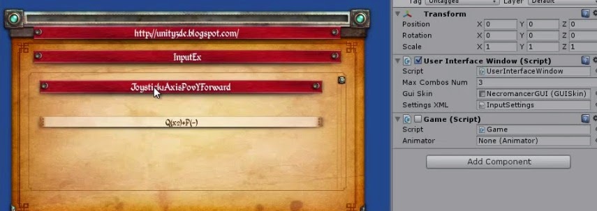
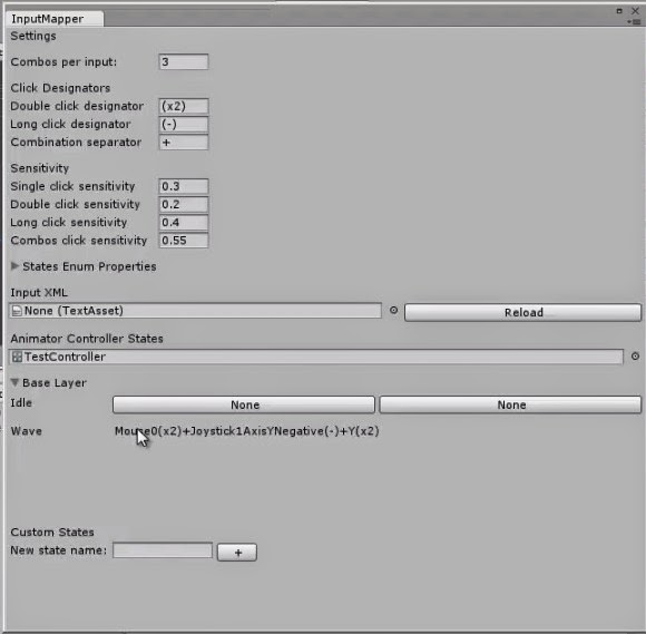
By just clicking keys/mouse/buttons or moving joystick, as SINGLE, DOUBLE and LONG. Primary and secondary. In the example below I've mapped Wave state combo of Mouse1 double clicks + Joystick1AxisYForward (Long push forward of the Joystick) + double click of letter Y.

You can set modifier format or clicks sensitivity. 


Clipboard01.jpg


8) Handling inputs by events
As the Update method gets overcrowded the library offers modern input handling solution by use of Event based system.

//Event Based input handling
InputEvent ev = new InputEvent("Click_W+C_State");
//InputEvent ev = new InputEvent((int)States.SomeState);
        
ev.CONT+=new EventHandler(Handle1);
ev.CONT+= new EventHandler(Handle2);
ev.UP += new EventHandler(onUp);//this wouldn't fire for combo inputs(single only)
ev.DOWN += new EventHandler(onDown);//this wouldn't fire for combo inputs(single only)
 

    void onUp(object o, EventArgs args)
    {
        Debug.Log("Up");
    }

    void onDown(object o, EventArgs args)
    {
        Debug.Log("Down");
    }

    void Handle1(object o, EventArgs args)
    {
        Debug.Log("Handle1");
    }

    void Handle2(object o, EventArgs args)
    {
        Debug.Log("Handle2");
    }

Hardcore developers can manually map input to states and even mix with loaded settings.

InputManager.loadSettings(Path.Combine(Application.streamingAssetsPath,"InputSettings.xml"));
     
//adding input-states pairs manually
InputManager.MapStateToInput("My State1",new InputCombination("Mouse1+Joystick12AxisXPositive(x2)+B"));

InputManager.MapStateToInput("Click_W+C_State", KeyCodeExtension.Alpha0.DOUBLE,KeyCodeExtension.JoystickAxisPovYPositive.SINGLE);

In KeyCodeExtension all KeyCode stuff are supported plus additional for Joystick Axis mapping.

9) Plug and play instead of plug and pray.
Attach or remove/switch controllers while game is running, remap inputs and continue playing.

10) Profiles - Layouts
Your homework.

Devices used during testing: XBox360W controller, ThrustMaster Wheel FFD, Wiimote + Nunchuk.
One classic Gamepad controller, one Wheel and complex controller.

19.08.14 Thrustmaster wheel RGT FFD demo WIN+DROID


GITHUB: https://github.com/winalex/Unity3d-InputMapper

Code is free if you contribute by solving a bug or enhance some version.!!!Joking :) Who can stop you/us.

Feedback, Forks are welcome if you aren't too smart, too movie star or too busy making money.

Gmail me as winxalex.

Knowledge should be free! 

13.07.2014 Added WiimoteDevice and WiimoteDriver Skeleton

22.07.2014 Quite more stability and plug in/out supported added.

26.07.2014 Web Player joystick support (Chrome, FireFox)


01.10.2014 WiiDevice and WiiDriver 


05.10.2014 XInput driver pure C# (No DirectX xinput.dll wrappers)

13.10.2014 (OSXDriver default driver pure C#)

17.10.2014 (Thrustmaster Wheel FFD and XBOX360W working on OSX) 


CONCEPT PROVED!!!

Throwing a Winning Pass

$
0
0
In a previous article, the problem of hitting a target with a fixed velocity was discussed and a solution described. In that case, the shooter had the ability to launch the projectile immediately at the direction where the target would eventually intercept it. While this is true for many cases, it is also true that the effect of having an AI turn and shoot at a moving target, and hit it, is more realistic and just plain awesome. It raises the bar significantly above "shoot at stuff" to "I can pick which target I want to hit, turn to shoot at it before it knows what's going on, and move on to the next target with ease." As you would expect, this does raise the bar a bit in the algorithm area.

Approaching the Problem


Looking at the picture below, it can be seen that the dynamics of the problem are very similar to the case from before.


Attached Image: post_images_hitting_targets_with_bullets2.png


The equations derived in the previous article still describe the situation:

(1) \(\vec{P_T^1} = \vec{P_T^0} + \vec{v_T} *(t_B+t_R)\)

(2) \((P_{Tx}^1 - P_{Sx})^2 +(P_{Ty}^1 - P_{Sy})^2 = S_b^2 * (t_B+t_R)^2\)

However, now instead of the time being just \(t_B\), the term includes \(t_R\), which is the amount of time needed to rotate through \(\theta_R\) radians.

Defining a few new variables:

  1. The unit vector for the "facing" direction of the shooter when the calculation begins: \(\hat{P_{ST}^0}\)
  2. The unit vector for the "facing" direction of the shooter when the shot is fired; this points towards \(\vec{P_T^1}\): \(\hat{P_{ST}^1}\)
  3. The rate at which the shooter rotates its body: \(\omega_R\)

When the body rotates at a rate of \(\omega_R\) for \(t_R\) seconds, it rotates through \(\theta_R\) radians.

\(\omega_R * t_R =\theta_R\)

Given the unit vectors defined above and using the definition of the dot product:

(3) \(\omega_R * t_R = acos(\hat{P_{ST}^0}\cdot\hat{P_{ST}^1})\)

In the previous case, the situation was "static". You fire the projectile and it heads towards a location. The only thing you need to know is the time of flight. But now you need to know how long you have to wait before you can shoot. But the longer you wait, the further your target will have traveled. So the solution "moves" as the rotation time increases.

That is a fairly "ugly" set of equations to try and solve. The static case's quadratic solution and evaluation of its descriminant gave us a good picture of the number of solutions possible. In this case, because of the quadratic/transcendental nature of the formuals, there may or may not be a closed form solution to it. So what do we do? Instead of asking ourselves how can we find the answer directly, ask ourselves how we would know if we found an answer that worked at all.

Pick A Number Between...


If we were to pick a random number for the total time, \(t_{impact} = t_R + t_B\), we could calculate the intercept position because that is how far the target would have traveled in that time, equation (1). Since we know the final position, we can calculate how far the projectile must have traveled to hit the target and also the time to rotate to that position from (2) and (3). If the value we chose for \(t_{impact}\) is a solution, then:

\(t_{impact} = t_R + t_B\)

But, if it is not, then \(t_{impact}\) will either be greater than or less than the sum. Using this, we can propose an answer, test it, and decide if that answer lies to the "left" or "right" of the proposed solution. Then propose (read: guess) again, using the answer we just got to get a little closer. Using this approach, we can iterate towards a solution in a (hopefully) bounded number of steps. Not as clean as a simple "plug and chug" formula, but very serviceable.

Binary Search


It is tempting to use a fast-converging numerical technique like Newton's Method to try and solve this. But the shape of the space that the solution lies in is unknown. We haven't even proven that the "left" or "right" decision process won't stick us in some thorny cyclic patch of non-convergence. Shooting off towards infinity on a small derivative estimate is also something that would be undesirable and hard to bound. We want this to be executed in an AI for a game that is running out in the field, not in a lab.

So, we're going to trade something that *might* converge faster for a search algorithm that will guarantee cutting the search space in half each time, the binary search. Here is how it will work:

  1. Define the minimum value, \(t_{min}\) that will be the smallest value for \(t_{impact}\) that will be allowed.
  2. Define the maximum value, \(t_{max}\) that will be the largest value for \(t_{impact}\) that will be allowed.
  3. Start with the value that is between the minimum and maximum as the first proposed value.
  4. Loop:
    1. Calculate the final impact location.
    2. Calculate the rotation time necessary to face the impact location, \(t_{rot}\).
    3. Calculate the flight time from the shooter to the final impact location, \(t_{flight}\).
    4. \(t_{shot} = t_{impact} - (t_{rot} + t_{flight})\)
    5. if \(t_{shot} > 0\), then set the upper limit to the proposed value and propose a new value between the upper and lower limits.
    6. if \(t_{shot} < 0\), then set the lower limit to the proposed value and propose a new value between the upper and lower limits.
    7. If the value of value of \(t_{impact}\) is changing within less than a specified tolerance, the algorithm has converged.
    8. If the number of loops gets too high, fail.
  5. Return success and the final position or failure.

The Code


The following function calculates whether or not the target can be hit and then returns the result. If the target could not be hit, the return value is "false". If it could, the return value is "true" and the solution, the position vector of the impact.

/* Calculate the future position of a moving target so that 
 * a turret can turn to face the position and fire a projectile.
 *
 * This algorithm works by "guessing" an intial time of impact
 * for the projectile 0.5*(tMin + tMax).  It then calculates
 * the position of the target at that time and computes what the 
 * time for the turret to rotate to that position (tRot0) and
 * the flight time of the projectile (tFlight).  The algorithms
 * drives the difference between tImpact and (tFlight + tRot) to 
 * zero using a binary search. 
 *
 * The "solution" returned by the algorithm is the impact 
 * location.  The shooter should rotate towards this 
 * position and fire immediately.
 *
 * The algorithm will fail (and return false) under the 
 * following conditions:
 * 1. The target is out of range.  It is possible that the 
 *    target is out of range only for a short time but in
 *    range the rest of the time, but this seems like an 
 *    unnecessary edge case.  The turret is assumed to 
 *    "react" by checking range first, then plot to shoot.
 * 2. The target is heading away from the shooter too fast
 *    for the projectile to reach it before tMax.
 * 3. The solution cannot be reached in the number of steps
 *    allocated to the algorithm.  This seems very unlikely
 *    since the default value is 40 steps.
 *
 *  This algorithm uses a call to sqrt and atan2, so it 
 *  should NOT be run continuously.
 *
 *  On the other hand, nominal runs show convergence usually
 *  in about 7 steps, so this may be a good 'do a step per
 *  frame' calculation target.
 *
 */
bool CalculateInterceptShotPosition(const Vec2& pShooter,
                                    const Vec2& vShooter,
                                    const Vec2& pSFacing0,
                                    const Vec2& pTarget0,
                                    const Vec2& vTarget,
                                    float64 sProjectile,
                                    float64 wShooter,
                                    float64 maxDist,
                                    Vec2& solution,
                                    float64 tMax = 4.0,
                                    float64 tMin = 0.0
                                    )
{
   cout << "----------------------------------------------" << endl;
   cout << " Starting Calculation [" << tMin << "," << tMax << "]" << endl;
   cout << "----------------------------------------------" << endl;
   
   float64 tImpact = (tMin + tMax)/2;
   float64 tImpactLast = tImpact;
   // Tolerance in seconds
   float64 SOLUTION_TOLERANCE_SECONDS = 0.01;
   const int MAX_STEPS = 40;
   for(int idx = 0; idx < MAX_STEPS; idx++)
   {
      // Calculate the position of the target at time tImpact.
      Vec2 pTarget = pTarget0 + tImpact*vTarget;
      // Calulate the angle between the shooter and the target
      // when the impact occurs.
      Vec2 toTarget = pTarget - pShooter;
      float64 dist = toTarget.Length();
      Vec2 pSFacing = (pTarget - pShooter);
      float64 pShootRots = pSFacing.AngleRads();
      float64 tRot = fabs(pShootRots)/wShooter;
      float64 tFlight = dist/sProjectile;
      float64 tShot = tImpact - (tRot + tFlight);
      cout << "Iteration: " << idx
      << " tMin: " << tMin
      << " tMax: " << tMax
      << " tShot: " << tShot
      << " tImpact: " << tImpact
      << " tRot: " << tRot
      << " tFlight: " << tFlight
      << " Impact: " << pTarget.ToString()
      << endl;
      if(dist >= maxDist)
      {
         cout << "FAIL:  TARGET OUT OF RANGE (" << dist << "m >= " << maxDist << "m)" << endl;
         return false;
      }
      tImpactLast = tImpact;
      if(tShot > 0.0)
      {
         tMax = tImpact;
         tImpact = (tMin + tMax)/2;
      }
      else
      {
         tMin = tImpact;
         tImpact = (tMin + tMax)/2;
      }
      if(fabs(tImpact - tImpactLast) < SOLUTION_TOLERANCE_SECONDS)
      {  // WE HAVE A WINNER!!!
         solution = pTarget;
         return true;
      }
   }
   return false;
}

Note:  The algorithm takes not only the position of the shooter, but its velocity as well. This is provision for a small modification where the shooter could be moving. In development of Star Crossing thus far, it has not been necessary to put in this modification. Feel free to let us know via feedback if you work it in (and it works for you).


The Video


Instead of cooking up a video just to demonstrate the basic use of the algorithm, it is going to be more effective to let you see it in action. The video below is a clip from a game we are actively working on called Star Crossing. In the clip, the ship pulls the Defense Drone behind it like a tail gunner. The Defense Drone turns to shoot at the Snakes as the ship drags it around. Go about a minute into the video and you'll see it.

Note:  This game is in work and the art is all drawn by hand to have something to look at while the mechanics are worked out. It looks pretty...well...crayolaish...that's not even a word but it probably has the right feel. If you would like to help the project with some art skill, feel free to contact us.


The Demo


I put together a small console application as a test bed to develop the algorithm initially. The simulation allows you to tinker with the parameters and see the running of the algorithm. You can download the source code for it using the link below. It is written in C++ and should compile on any modern compiler. We used XCode on a Macbook Pro, but the code has no graphics or special libraries associated with it.

The (Rest of the) Code


Get the Source Code for this article hosted on GitHub by clicking here.

Interesting Points

  • While there is a bound on the algorithm, it usually converges in less than 10 steps in our testing.
  • (Proposed...not proven) Knowing your turn rate in radians/sec, you can modify the SOLUTION_TOLERANCE_SECONDS value so that it converges to a resoluion in terms of arc seconds from the target. That is to say, you don't have to shoot dead at the target positiion to hit it, you just have to be really close. This gives you a good way to set your tolerance and save some loops. You could change the algorithm to take a tolerance in degrees or radians to set the convergence limit.
  • You need to handle the case where the target is heading right at you. We use the dot product for this and just "fire now". This is done before the algorithm is even called.
  • Our initial algorithm shot at the location of the target instead of leading it. When we put the new algorithm into effect at first, it was not too exciting, but much better. When we put in the "shoot if it is in front of you" addition, the combo pack was devastating and we had to turn down the Defense Drone weapon power to stop it from decimating the snakes too fast. Be careful what you wish for.
  • While I haven't tried it, it seems reasonable you could pick a "better" start value for \(t_{impact}\) by using the non-rotating solution plus a little slop time (maybe the amount of time to rotate to face that position). This has the right "feel" for an initial estimate and seems worth exploring in the future.

Conclusion


This article presented an approach for predicting the future position of a moving target based on having to rotate to shoot it. A simulation of using the algorithm was also created for you to tinker with. The solution appears to work well for our current needs.

Article Update Log

30 October 2014: Initial release

What's In Your Toolbox?

$
0
0
Big things are made of little things. Making things at all takes tools. We all know it is not the chisel that creates the sculpture, but the hand that guides it. Still, having a pointy chisel is probably better to break the rock than your hand.

In this article, I'll enumerate the software tools that I use to put together various parts of my software. I learned about these tools by reading sites like this one, so feel free to contribute your own. I learned how to use them by setting a small goal for myself and figuring out whether or not the tool could help me achieve it. Some made the cut. Some did not. Some may be good for you. Others may be good for you.

Software Tools


#NameUsed ForCostLinkNotes
1Cocos2d-xC++ Graphical FrameworkFreewww.cocos2d-x.orgHas lots of stuff out of the box and a relatively light learning curve. We haven't used it cross-platform (yet) but many have before us, so no worries.
2Box2D2-D PhysicsFreewww.box2d.orgNo longer the default for cocos2d-x :( but still present in the framework. I still prefer it over Chipmunk. Now you know at least two to try...
3GimpBitmap Graphics EditorFreewww.gimp.orgAbove our heads but has uses for slicing, dicing, and mutilating images. Great for doing backgrounds.
4InkscapeVector Graphics EditorFree
www.inkscape.orgOur favorite tool for creating vector graphics. We still suck at it, but at least the tool doesn't fight us.
5PaperGraphics Editor (iPad)~$10App StoreThis is an incredible sketching tool. We use it to generate graphics, spitball ideas for presentations, and create one-offs for posts.
6SpineSkeletal Animation~$100www.esotericsoftware.comI *wish* I had enough imagination to get more out of this incredible tool.
7Physics EditorSee Notes$20www.codeandweb.comCreates data to turn images into data that Box2D can use. Has some annoyances but very solid on the whole.
8Texture PackerSee Notes$40www.codeandweb.comPuts images together into a single file so that you can batch them as sprites.
9PythonScripting LanguageFreewww.python.orgAt some point you will need a scripting language to automate something in your build chain. We use python. You can use whatever you like.
10Enterprise ArchitectUML Diagrams~$130-$200www.sparxsystems.comYou probably won't need this but we use it to create more sophisticated diagrams when needed. We're not hard core on UML, but we are serious about ideas and a picture is worth a thousand words.
11ReflectorSee Notes~$15Mac App StoreThis tool lets you show your iDevice screen on your Mac. Which is handy for screen captures without the (very slow) simulator.
12XCodeIDEFreeMac App StoreCocos2d-x works in multiple IDEs. We are a Mac/Windows shop. Game stuff is on iPads, so we use XCode. Use what works best for you.
13Glyph DesignerSee Notes$40www.71squared.comCreates bitmapped fonts with data. Seamless integration with Cocos2d-x. Handy when you have a lot of changing text to render.
14Particle DesignerSee Notes$60www.71squared.comHelps you design the parameters for particle emitter effects. Not sure if we need it for our stuff but we have used these effects before and may again. Be sure to block out two hours of time...the temptation to tweak is incredible.
15Sound BibleSee NotesFreewww.soundbible.comGreat place to find sound clips. Usually the license is just attribution, which is a great karmic bond.
16Tiled QTSee NotesFreewww.mapeditor.orgA 2-D map editor. Cocos2d-x has import mechanisms for it. I haven't needed it, but it can be used for tile/orthogonal map games. May get some use yet.

Conclusion


A good developer (or shop) uses the tools of others as needed, and develops their own tools for the rest. The tools listed here are specifically software that is available "off the shelf". I did not list a logging framework (because I use my own) or a unit test framework (more complex discussion here) or other "tools" that I have picked up over the years and use to optimize my work flow.

I once played with Blender, the fabulous open-source 3-D rendering tool. It has about a million "knobs" on it. Using it, I realized I was easily overwhelmed by it, but I also realized that my tools could easily overwhelm somebody else if they were unfamiliar with them and did not take the time to figure out how to get the most out of them.

The point of all this is that every solid developer I know figures out the tools to use in their kit and tries to get the most out of them. Not all hammers fit in all hands, though.

Article Update Log


5 Nov 2014: Initial Release

A Room With A View

$
0
0
A Viewport allows for a much larger and richer 2-D universe in your game. It allows you to zoom in, pan across, and scale the objects in your world based on what the user wants to see (or what you want them to see).

The Viewport is a software component (written in C++ this time) that participates in a larger software architecture. UML class and sequence diagrams (below) show how these interactions are carried out.

The algorithms used to create the viewport are not complex. The ubiquitous line equation, y = m.x + b, is all that is needed to create the effect of the Viewport. The aspect ratio of the screen is also factored in so that "squares can stay squares" when rendered.

Beyond the basic use of the Viewport, allowing entities in your game to map their position and scale onto the display, it can also be a larger participant in the story your game tells and the mechanics of making your story work efficiently. Theatrical camera control, facilitating the level of detail, and culling graphics operations are all real-world uses of the Viewport.

NOTE: Even though I use Box2D for my physics engine, the concepts in this article are independent of that or even using a physics engine for that matter.

The Video


The video below shows this in action.


The Concept


The world is much bigger than what you can see through your eyes. You hear a sound. Where did it come from? Over "there". But you can't see that right now. You have to move "there", look around, see what you find. Is it an enemy? A friend? A portal to the bonus round? By only showing your player a portion of the bigger world, they are goaded into exploring the parts they cannot see. This way lies a path to immersion and entertainment.

A Viewport is a slice of the bigger world. The diagram below shows the basic concept of how this works.


Attached Image: Viewport-Concept.png


The Game World (left side) is defined to be square and in meters, the units used in Box2D. The world does not have to be square, but it means one less parameter to carry around and worry about, so it is convenient.

The Viewport itself is defined as a scale factor of the respective width/height of the Game World. The width of the Viewport is scaled by the aspect ratio of the screen. This makes it convenient as well. If the Viewport is "square" like the world, then it would have to lie either completely inside the non-square Device Screen or with part of it completely outside the Device Screen. This makes it unusable for "IsInView" operations that are useful (see Other Uses at the end).

The "Entity" is deliberately shown as partially inside the Viewport. When displayed on the Device Screen, it is also only shown as partially inside the view. Its aspect on the screen is not skewed by the size of the screen relative to the world size. Squares should stay squares, etc.

The "nuts and bolts" of the Viewport are linear equations mapping the two corner points (top left, bottom right) in the coordinate system of the world onto the screen coordinate system. From a "usage" standpoint, it maps the positions in the simulated world (meters) to a position on the screen (pixels). There will also be times when it is convenient to go the other way and map from pixels to meters. The Viewport class handles the math for the linear equations, computing them when needed, and also provides interfaces for the pixel-to-meter or meter-to-pixel transformations.

Note that the size of the Game World used is also specifically ambiguous. The size of all Box2D objects should be between 0.1m and 10m, the world can be much larger as needed and within realistic use of the float32 precision used in Box2D. That being said, the Viewport size is based on a scale factor of the Game World size, but it is conceivable (and legal) to move the Viewport outside of the "established" Game World size. What happens when you view things "off the grid" is entirely up to your game design.

Classes and Sequences


The Viewport does not live by itself in the ecosystem of the game architecture. It is a component that participates in the architecture. The diagram below shows the major components used in the Missile Demo application.


Attached Image: Missile-Demo-Main-Components.png


The main details of each class have been omitted; we're more interested in the overall component structure than internal APIs at this point.

Main Scene


The MainScene (top left) is the container for all the visual elements (CCLayer-derived objects) and owner of an abstract interface, the MovingEntityIFace. Only one instance exists at a time. The MainScene creates a new one when signaled by the DebugMenuLayer (user input) to change the Entity. Commands to the Entity are also executed via the MainScene. The MainScene also acts as the holder of the Box2D world reference.

Having the MainScene tie everything together is perfectly acceptable for a small single-screen application like this demonstration. In a larger multi-scene system, some sort of UI Manager approach would be used.

Viewport and Notifier


The Viewport (lower right) is a Singleton. This is a design choice. The motivations behind it are:
  • There is only one screen the user is looking at.
  • Lots of different parts of the graphics system may use the Viewport.
  • It is much more convenient to do it as a "global" singleton than to pass the reference around to all potential consumers.
  • Deriving it from the SingletonDynamic template ensures that it follows the Init/Reset/Shutdown model used for all the Singleton components. It's life cycle is entirely predictable: it always exists.
The Notifier is also pictured to highlight its importance; it is an active participant when the Viewport changes. The diagram below shows exactly this scenario.


Attached Image: Pinch-Changes-Viewport.png


The user user places both fingers on the screen and begins to move them together (1.0). This move is received by the framework and interpreted by the TapDragPinchInput as a Pinch gesture, which it signals to the MainScene (1.1). The MainScene calls SetCenter on the Viewport (1.2) which immediately leads to the Viewport letting all interested parties know the view is changing via the Notifier (1.3). The Notifier immediately signals the GridLayer, which has registered for the event (1.4). This leads to the GridLayer recalculating the position of its grid lines (1.5). Internally, the GridLayer maintains the grid lines as positions in meters. It will use the Viewport to convert these to positions in pixels and cache them off. The grid is not actually redrawn until the next draw(...) call is executed on it by the framework.

The first set of transactions were executed synchronously as the user moved their fingers; each time a new touch event came in, the change was made. The next sequence (starting with 1.6) is initiated when the framework calls the Update(...) method on the main scene. This causes an update of the Box2D physics model (1.7). At some point later, the framework calls the draw(...) method on the Box2dDebugLayer (1.8). This uses the Viewport to calculate the display positions of all the Box2D bodies (and other elements) it will display (1.9).

These two sequences demonstrate the two main types of Viewport update sequences. The first is triggered by the a direct change of the view leading to events that trigger immediate updates. The second is called by the framework every major update of the model (as in MVC).

Algorithms


The general method for mapping the world space limits (Wxmin, Wxmax) onto the screen coordinates (0,Sxmax) is done by a linear mapping with a y = mx + b formulation. Given the two known points for the transformation:

Wxmin (meters) maps onto (pixel) 0 and
Wxmax (meters) maps onto (pixel) Sxmax
Solving y0 = m*x0 + b and y1 = m*x1 + b1 yields:

m = Sxmax/(Wxmax - Wxmin) and
b = -Wxmin*Sxmax/(Wxmax - Wxmin) (= -m * Wxmin)

We replace (Wxmax - Wxmin) with scale*(Wxmax-Wxmin) for the x dimension and scale*(Wymax-Wymin)/aspectRatio in the y dimension.

The value (Wxmax - Wxmin) = scale*worldSizeMeters (xDimension)

The value Wxmin = viewport center - 1/2 the width of the viewport

etc.

In code, this is broken into two operations. Whenever the center or scale changes, the slope/offset values are calculated immediately.

void Viewport::CalculateViewport()
{
   // Bottom Left and Top Right of the viewport
   _vSizeMeters.width = _vScale*_worldSizeMeters.width;
   _vSizeMeters.height = _vScale*_worldSizeMeters.height/_aspectRatio;

   _vBottomLeftMeters.x = _vCenterMeters.x - _vSizeMeters.width/2;
   _vBottomLeftMeters.y = _vCenterMeters.y - _vSizeMeters.height/2;
   _vTopRightMeters.x = _vCenterMeters.x + _vSizeMeters.width/2;
   _vTopRightMeters.y = _vCenterMeters.y + _vSizeMeters.height/2;

   // Scale from Pixels/Meters
   _vScalePixelToMeter.x = _screenSizePixels.width/(_vSizeMeters.width);
   _vScalePixelToMeter.y = _screenSizePixels.height/(_vSizeMeters.height);

   // Offset based on the screen center.
   _vOffsetPixels.x = -_vScalePixelToMeter.x * (_vCenterMeters.x - _vScale*_worldSizeMeters.width/2);
   _vOffsetPixels.y = -_vScalePixelToMeter.y * (_vCenterMeters.y - _vScale*_worldSizeMeters.height/2/_aspectRatio);

   _ptmRatio = _screenSizePixels.width/_vSizeMeters.width;

   Notifier::Instance().Notify(Notifier::NE_VIEWPORT_CHANGED);
}

Note:  Whenever the viewport changes, we emit a notification to the rest of the system to let interested parties react. This could be broken down into finer detail for changes in scale vs. changes in the center of the viewport.


When the a conversion from world space to viewport space is needed:

CCPoint Viewport::Convert(const Vec2& position)
{
   float32 xPixel = position.x * _vScalePixelToMeter.x + _vOffsetPixels.x;
   float32 yPixel = position.y * _vScalePixelToMeter.y + _vOffsetPixels.y;
   return ccp(xPixel,yPixel);
}

And, occasionally, we need to go the other way.

/* To convert a pixel to a position (meters), we invert
 * the linear equation to get x = (y-b)/m.
 */
Vec2 Viewport::Convert(const CCPoint& pixel)
{
   float32 xMeters = (pixel.x-_vOffsetPixels.x)/_vScalePixelToMeter.x;
   float32 yMeters = (pixel.y-_vOffsetPixels.y)/_vScalePixelToMeter.y;
   return Vec2(xMeters,yMeters);
}

Position, Rotation, and PTM Ratio


Box2D creates a physics simulation of objects between the sizes of 0.1m and 10m (according to the manual, if the scaled size is outside of this, bad things can happen...the manual is not lying). Once you have your world up and running, you need to put the representation of the bodies in it onto the screen. To do this, you need its rotation (relative to x-axis), position, and a scale factor to convert the physical meters to pixels. Let's assume you are doing this with a simple sprite for now.

The rotation is the easiest. Just ask the b2Body what its rotation is and convert it to degrees with CC_RADIANS_TO_DEGREES(...). Use this for the angle of your sprite.

The position is obtained by asking the body for its position in meters and calling the Convert(...) method on the Viewport. Let's take a closer look at the code for this.

/* To convert a position (meters) to a pixel, we use
 * the y = mx + b conversion.
 */
CCPoint Viewport::Convert(const Vec2& position)
{
   float32 xPixel = position.x * _vScalePixelToMeter.x + _vOffsetPixels.x;
   float32 yPixel = position.y * _vScalePixelToMeter.y + _vOffsetPixels.y;
   return ccp(xPixel,yPixel);
}

This is about as simple as it gets in the math arena. A linear equation to map the position from the simulated physical space (meters) to the Viewport's view of the world on the screen (pixels). A key nuance here is that the scale and offset are calculated ONLY when the viewport changes.

The scale is called the pixel-to-meter ratio, or just PTM Ratio. If you look inside the CalculateViewport method, you will find this rather innocuous piece of code:

   _ptmRatio = _screenSizePixels.width/_vSizeMeters.width;

The PTM Ratio is computed dynamically based on the size of the width viewport (_vSizeMeters). Note that it could be computed based on the height instead; be sure to define the aspect ratio, etc., appropriately.

If you search the web for articles on Box2D, whenever they get to the display portion, they almost always have something like this:

#define PTM_RATIO 32

Which is to say, every physical body is represented by a ratio of 32 pixels (or some other value) for each meter in the simulation. The original iPhone screen was 480 x 320, and Box2D represents objects on the scale of 0.1m to 10m, so a full sized object would take up the full width of the screen. However, it is a fixed value. Which is fine.

Something very interesting happens though, when you let this value change. By letting the PTM Ratio change and scaling your objects using it, the viewer is given the illusion of depth. They can move into and out of the scene and feel like they are moving into and out of the scene in the third dimension.

You can see this in action when you use the pinch operation on the screen in the App. The Box2DDebug uses the Viewport's PTM Ratio to change the size of the displayed polygons. It can (and has) been used to also scale sprites so that you can zoom in/out.

Other Uses


With a little more work or a few other components, the Viewport concept can be expanded to yield other benefits. All of these uses are complementary. That is to say, they can all be used at the same time without interfering with each other.

Camera


The Viewport itself is "Dumb". You tell it change and it changes. It has no concept of time or motion; it only executes at the time of command and notifies (or is polled) as needed. To execute theatrical camera actions, such as panning, zooming, or combinations of panning and zooming, you need a "controller" for the Viewport that has a notion of state. This controller is the camera.

Consider the following API for a Camera class:

class Camera
{
public:
   // If the camera is performing any operation, return true.
   bool IsBusy();

   // Move/Zoom the Camera over time.
   void PanToPosition(const vec2& position, float32 seconds);
   void ZoomToScale(float32 scale, float32 seconds);

   // Expand/Contract the displayed area without changing
   // the scale directly.
   void ExpandToSize(float32 size, float32 seconds);

   // Stop the current operation immediately.
   void Stop();

   // Called every frame to update the Camera state
   // and modify the Viewport.  The dt value may 
   // be actual or fixed in a fixed timestep
   // system.
   void Update(float32 dt);
};

This interface presents a rudimentary Camera. This class interacts with the Viewport over time when commanded. You can use this to create cut scenes, quickly show items/locations of interest to a player, or other cinematic events.

A more sophisticated Camera could keep track of a specific entity and move the viewport automatically if the the entity started to move too close to the viewable edge.

Level of Detail


In a 3-D game, objects that are of little importance to the immediate user, such as objects far off in the distance, don't need to be rendered with high fidelity. If it is only going to be a "dot" to you, do you really need 10k polygons to render it? The same is true in 2-D as well. This is the idea of "Level of Detail".

The PTMRatio(...) method/member of the Viewport gives the number of pixels an object will be given its size in meters. If you use this to adjust the scale of your displayed graphics, you can create elements that are "sized" properly for the screen relative to the other objects and the zoom level. You can ALSO substitute other graphics when the displayed object will appear to be little more than a blob. This can cut down dramatically on the GPU load and improve the performance of your game.

For example, in Space Spiders Must Die!, each Spider is not single sprite, but a group of sprites loaded from a sprite sheet. This sheet must be loaded into the GPU, the graphics drawn, then another sprite sheet loaded in for other objects. When the camera is zoomed all the way out, we could get a lot more zip out of the system if we didn't have to swap out the sprite sheet at all and just drew a single sprite for each spider. A much smaller series of "twinkling" sprites could easily replace the full-size spider.

Culling Graphics Operations


If an object is not in view, why draw it at all? Well...you might still draw it...if the cost of keeping it from being drawn exceeds the cost of drawing it. In Cocos2D-x, it can get sticky to figure out whether or not you are really getting a lot by "flagging" elements off the screen and controlling their visibility (the GPU would probably handle it from here).

However, there is a much less-ambiguous situation: Skeletal Animations. Rather than use a lot of animated sprites (and sprite sheets), we tend to use Spine to create skeletal animated sprites. These absolutely use a lot of calculations which are completely wasted if you can't see the animation because it is off camera. To save CPU cycles, which are even more limited these days than GPU cycles for the games we make, we can let the AI for the animiation keep running but only update the "presentation" when needed.

The Viewport provides a method called IsInView(...) just for this purpose. Using it, you can flag entities as "in view" or "not in view". Internally, the representation used for the entity can make the decision to update or not based on this.

Conclusion


A Viewport has uses that allows you to create a richer world for the player to "live" in, both by providing "depth" via zooming and allowing you to keep content outside the Viewport. It also provides opportunities to improve the graphics processing efficiency of your game.

Get the Source Code for the this post hosted on GitHub by clicking here.

Article Update Log


6 Nov 2014: Initial release

Creating a Very Simple GUI System for Small Games - Part I

$
0
0
If you are writing your own game, sooner or later you will need some sort of user interface (or graphic user interface = GUI). There are some existing libraries lying around. Probably the most famous is CEGUI, that is also easy to integrate into OGRE 3D engine. A good looking system was also LibRocket, but its development stopped in 2011 (but you can still download and use it without any problem). There are a lot of discussion threads that deal with the eternal problem “What GUI should I use?”.

Not so long ago I faced the very same problem. I needed a library written in C++ that would be able to coexist with OpenGL and DirectX. Another requirement was support for classic (mouse) control as well as touch input. CEGUI seems to be good choice, but the problem is in its complexity and not so great touch support (from what I was told). Most of the time, I just need a simple button, check box, text caption and “icon” or image. With those, you can build almost anything. As you may know, GUI is not just what you can see. There is also functionality, like what happens if I click on a button, if I move mthe ouse over an element etc. If you choose to write your own system, you will have to also implement those and take into account that some of them are only for mouse control and some of them are only for touch (like more than one touch at a time).

Writing a GUI from scratch is not an easy thing to do. I am not going to create some kind of super-trooper complex system that will handle everything. Our designed GUI will be used for static game menu controls and in-game menus. You can show scores, lives and other info with this system. An example of what can be created with this simple system can be seen in figures 1 and 2. Those are actuals screen-shots from engines and games I have created with this.


Attached Image: 0C__Martin_Programing_OpenGL-ES_Tutorials_GUI_simple_gui.png

Attached Image: 1C__Martin_Programing_OpenGL-ES_Tutorials_GUI_screen3.png


Our GUI will be created in C++ and will work with either OpenGL or DirectX. We are not using any API-specific things. Apart from plain C++, we also will need some libraries that make things easier for us. One of the best “library” (it's really just a single header file) - FastDelegate - will be used for function pointers (we will use this for triggers). For rendering of fonts, I have decided to use the FreeType2 library. It's a little more complex, but it's worth it. That is pretty much all you need. If you want, you can also add support for various image formats (jpg, png...). For simplicity I am using tga (my own parser) and png (via not so fast, but easy to use LodePNG library).

Ok. You have read some opening sentences and it's time to dig into details.

You can also look at following chapters:

Coordinate System and Positioning


The most important thing of every GUI system is positioning of elements on your screen. Graphics APIs are using screen space coordinates in range [-1, 1]. Well... it's good, but not really good if we are creating / designing a GUI.

So how to determine the position of an element? One option is to use an absolute system, where we set real pixel coordinates of an element. Simple, but not really usable. If we change resolution, our entire beautifully-designed system will go to hell. Hm.. second attempt is to use a relative system. That is much better, but also not 100%. Let's say we want to have some control elements at the bottom of the screen with a small offset. If relative coordinates are used, the space will differ depending on resolution which is not what we usually want.

What I used at the end is a combination of both approaches. You can set position in relative and absolute coordinates. That is somewhat similar to the solution used in CEGUI.

Steps described above were applied on the entire screen. During GUI design there is a very little number of elements that will meet this condition. Most of the time, some kind of panel is created and other elements are placed on this panel. Why? That's simple. If we move the panel, all elements on it move along with it. If we hide the panel, all elements hide with it. And so on.

What I write so far for positioning is perfectly correct for this kind of situations as well. Again, a combination of relative and absolute positioning is used, but this time the relative starting point is not [0,0] corner of entire screen, but [0,0] of our “panel”. This [0,0] point already has some coordinates on screen, but those are not interesting for us. A picture is worth a thousand words. So, here it is:


Attached Image: 2C__Martin_Programing_OpenGL-ES_Tutorials_GUI_positioning.png
Figure 3: Position of elements. Black color represents screen (main window) and position of elements within it. Panel is positioned within Screen. Green element is inside Panel. It's positions are within Panel.


That is, along with hard offsets, the main reason why I internally store every position in pixels and not in relative [0, 1] coordinates (or simply in percents). I once calculated pixel position and I don't need to have several recalculations of percents based on an element's parent and real pixel offsets. Disadvantage of this is that if the screen size is changed, the entire GUI needs to be reloaded. But let's be honest, how often do we change the resolution of a graphics application ?

If we are using some graphics API (either OpenGL or DirectX), rendering is done in screen space and not in pixels. Screen space is similar to percents, but has the range [-1,1]. Conversion to the screen space coodinates is done as the last step just before uploading data to the GPU. A pipeline of transforming points to the screen space coordinates is shown on the following three equations. Input pixel is converted to point in range [0, 1] by simply dividing pixel position by screen resolution. From point in [0, 1], we map it to [-1, 1].

pixel = [a, b]
point = [pixel(a) / width, pixel(b) / height]
screen_space = 2 * point - 1    

If we want to use the GUI without a graphics API, lets say do it in Java, C#... and draw elements into image, you can just stick with pixels.

Anchor System

All good? Good. Things will be little more interesting from now on. A good thing in GUI design is to use anchors. If you have ever created a GUI, you know what anchors are. If you want to have your element stickied to some part of the screen no matter the screen size, that's the way you do it - anchors. I have decided to use a similar but slighty different system. Every element I have has its own origin. This can be one of the four corners (top left - TL, top right - TR, bottom left - BL, bottom right - BR) or its center - C. The position you have entered is than relative to this origin. Default system is TL.


Attached Image: 3C__Martin_Programing_OpenGL-ES_Tutorials_GUI_gui1.png
Figure 4: Anchors of screen elements


Let's say you want your element always to be sticked in the bottom right corner of your screen. You can simulate this position with TL origin and the element's size. Better solution is to go backward. Position your element in a system with changed origin and convert it to TL origin later (see code). This has one advantage: you will keep user definition of GUI unified (see XML snippet) and it will be more easy to maintain.

<position x="0" y="0" offset_x="0" offset_y="0" origin="TL" />     
<position x="0" y="0" offset_x="0" offset_y="0" origin="TR" />     
<position x="0" y="0" offset_x="0" offset_y="0" origin="BL" />     
<position x="0" y="0" offset_x="0" offset_y="0" origin="BR" />  

All In One

In the following code, you can see full calculation and transformation from user input (eg. from above XML) into internal element coordinate system, that is using pixels. First, we calculate pixel position of the corner as provided by our GUI user. We also need to calculate element width and height (proportions of elements will be discussed further in the next part). For this, we need proportions of the parent - meaning its size and pixel coordinate of TL corner.

float x = parentProportions.topLeft.X; 		
x += pos.x * parentProportions.width; 		
x += pos.offsetX; 
		
float y = parentProportions.topLeft.Y; 		
y += pos.y * parentProportions.height; 		
y += pos.offsetY;

float w = parentProportions.width; 		
w *= dim.w; 		
w += dim.pixelW;
		
float h = parentProportions.height; 		
h *= dim.h; 		
h += dim.pixelH;	

For now, we have calculated the pixel position of our reference corner. However, internal storage of our system must be unified, so everything will be converted to a system with [0,0] in TL.

//change position based on origin 		
if (pos.origin == TL)  		
{ 
   //do nothing - top left is default 
} 		
else if (pos.origin == TR)  		
{ 
	x = parentProportions.botRight.X - (x - parentProportions.topLeft.X); //swap x coordinate 				
	x -= w; //put x back to top left 			
} 		
else if (pos.origin == BL)  		
{ 			
	y = parentProportions.botRight.Y - (y - parentProportions.topLeft.Y); //swap y coordinate 			
	y -= h; //put y back to top left 					
} 		
else if (pos.origin == BR)  		
{ 			
	x = parentProportions.botRight.X - (x - parentProportions.topLeft.X); //swap x coordinate				
	y = parentProportions.botRight.Y - (y - parentProportions.topLeft.Y); //swap y coordinate
	x -= w; //put x back to top left 			
	y -= h; //put y back to top left		
}
else if (pos.origin == C)  		
{
	//calculate center of parent element 			
	x = x + (parentProportions.botRight.X - parentProportions.topLeft.X) * 0.5f; 
	y = y + (parentProportions.botRight.Y - parentProportions.topLeft.Y) * 0.5f; 			
	x -= (w * 0.5f); //put x back to top left						
	y -= (h * 0.5f); //put y back to top left
}
		
//this will overflow from parent element 		
proportions.topLeft = MyMath::Vector2(x, y); 
proportions.botRight = MyMath::Vector2(x + w, y + h); 		
proportions.width = w; 
proportions.height = h;

With the above code, you can easily position elements in each corner of a parent element with almost the same user code. We are using float instead of int for pixel coordinate representations. This is OK, because at the end we transform this to screen space coordinates anyway.

Proportions


Once we established position of an element, we also need to know its size. Well, as you may remember, we have already needed proportions for calculating the element's position, but now we discuss this topic a bit more.

Proportions are very similar to positioning. We again use relative and absolute measuring. Relative numbers will give us size in percents of parent and pixel offset is, well, pixel offset. We must take in mind one important thing - aspect ratio (AR). We want our elements to keep it every time. It would not be nice if our icon was correct on one system and deformed on another. We can repair this by only specifying one dimension (width or height) and the relevant aspect ratio for this dimension.

See the difference in example below:

a) <size w="0.1" offset_w="0" ar="1.0" /> - create element of size 10% of parent W
b) <size w="0.1" h="0.1" offset_w="0" offset_h="0" /> - create element of size 10% of parent W and H

Both of them will create an element with the same width. Choice a) will always have correct AR, while choice b) will always have the same size in respect of its parent element.

While working with relative size, it is also a good thing to set some kind of maximal element size in pixels. We want some elements to be as big as possible on small screens but its not neccessary to have them oversized on big screens. A typical example will be phone and tablet. There is no need for an element to be extremly big (eg. occupy let's say 100x100 pixels) on a tablet. It can take 50x50 as well and it will be enough. But on smaller screens, it should take as much as possible according to our relative size from user input.

Fonts


Special care must be taken for fonts. Positioning and proportions differ a little from classic GUI elements. First of all, for font positioning it is often good to put origin into its center. That way, we can center very easily fonts inside parent elements, for example buttons. As mentioned before, to recalculate position from used system into system with TL origin, we need to know the element size.


Attached Image: 4C__Martin_Programing_OpenGL-ES_Tutorials_GUI_font_center.png
Figure 5: Origin in center of parent element for centered font positioning


That is the tricky part. When dealing with text, we are setting only height and the width will depend on various factors - used font, font size, printed text etc. Of course, we can calculate size manually and use it later, but that is not correct. During runtime, text can change (for instance the score in our game) and what then? A better approach is to recalculate position based on text change (change of text, font, font size etc.).

As I mentioned, for fonts I am using the FreeType library. This library can generate a single image for each character based on used font. It doesn´t matter if we have pregenerated those images into font atlas textures or we are creating them on the fly. To calculate proportions of text we don't really need an actual image, but only its size. Problem is size of the whole text we want to display. This must be calculated by iterating over every character and accumulating proportions and spaces for each of them. We also must take care of new lines.

There is one thing you need to count on when dealing with text. See the image and its caption below. Someone may think that answer to “Why?” question is obvious, but I didn't realize that in time of design and coding, so it brings me a lot of headache.


Attached Image: 5C__Martin_Programing_OpenGL-ES_Tutorials_GUI_HL2zV.png
Figure 6: Text rendered with settings: origin is TL (top left), height is set to be 100% of parent height. You may notice, text is not filling the whole area. Why ?


The answer is really simple. There are diacritics marks in the text that are counted in total size. There should also be space for descendents, but they are not used for capitals in the font I have used. Everything you need to take care of can be seen in this picture:


Attached Image: 6C__Martin_Programing_OpenGL-ES_Tutorials_GUI_tEt8J.png
Figure 7: Font metrics


Discussion


This will be all for now. I have described the basics of positioning and sizing of GUI elements that I have used in my design. There are probably better or more complex ways to do it. This one used here is easy and I have not run across any problems using it.

I have written a simple C# application to speed up the design of the GUI. It uses the basics described here (but no fonts). You can place elements, change their size and image, drag them to see positions of them. You can download the source of application and try it for yourself. But take it as “alpha” version, I have written it for fast prototyping during one evening.

In future parts (don't worry, I have already written them and only doing finishing touches) I will focus on basic types of elements, controls, rendering. That is, after all, one of the important things in GUI :-)

Article Update Log


22 May 2014: Added links to following parts
3 May 2014: Initial release

Visual Tools For Debugging Games

$
0
0

Overview


How much of your time do you spend writing code? How much of your time you spend fixing code?

Which would you rather be doing? This is a no-brainer, right?

As you set out to develop a game, having a strategy for how you are going to illuminate the "huh?" moments well before you are on the 15th level is going to pay dividends early and often in the product life cycle. This article discusses strategies and lessons learned from debugging the test level for the 2D top down shooter, Star Crossing.


Attached Image: iPad_1.png


Intrinsic Tools


Before discussing the tools you do not have by default, it seems prudent to list out the ones you will generally have available in most modern development tool chains.
  • Console output via printf(...). With more advanced loggers built into your code base, you can generate oceans worth of output or a gentle trickle of nuanced information as needed. Or you can just have it print "here 1", "here 2", etc. To get output, you have to actually put in code just for the purpose of outputting it. This usually starts with some basic outputs for things you know are going to be helpful, then degenerates into 10x the number of logging messages for specific issues you are working on.
  • Your actual "debugger", which allows you to set breakpoints, inspect variables, and gnash your teeth at when you try to have it display the contents of a std::map. This is your first line of defense and probably the one you learned to use in your crib.
  • A "profiler" which allows you to pinpoint where your code is sucking down the frame rate. You usually only break this out (1) when things go really wrong with your frame rate, (2) when you are looking for that memory leak that is crashing your platform, or (3) when your boss tells you to run before shipping even though the frame rate is good and the memory appears stable, because you don't really know if the memory is stable until you check.
All these tools are part of the total package you start out with (usually). They will carry you well through a large part of the development, but will start to lose their luster when you are debugging AI, physics, etc. That is to say, when you are looking at stuff that is going on in real time, it is often very hard to put the break point at the right place in the code or pull useful information from the deluge of console output.

Random Thoughts


If your game has randomness built into it (e.g. random damage, timeouts, etc.), you may run into serious trouble duplicating failure modes. Someone may even debate whether the randomness is adding value to your game because of the headaches associated with debugging it. As part of the overall design, a decision was made early on to enable not-so-random-randomness as follows:
  • A "cycle clock" was constructed. This is lowest "tick" of execution of the AI/Physics of the game.
  • The cycle clock was set to 0 at the start of every level, and proceeded up from there. There is, of course, the possibility that the game may be left running forever and overflow the clock. Levels are time limited, so this is not a concern here (consider yourself caveated).
  • A simple static class provided the API for random number generation and setting the seed of the generator. This allowed us to put anything we want inside of the generation so the "clients" did not know or care what the actual "rand" function was.
  • At the start of every tick, the tick value was used to initialize the seed for the random number system.
This allowed completely predictable random number generation for the purposes of debugging. This also has an added benefit, if it stays in the game, of the game evolving in a predictable way, at least at the start of a level. Once the user generates their own "random input", all bets are off.

Pause, Validate, Continue


The screenshot below shows a scene from the game with only the minimal debugging information displayed, the frame rate.


Attached Image: iPad_1a.png


The first really big problem with debugging a real-time game is that, well, it is going on in real-time. In the time it takes you to take your hand off the controls and hit the pause button (if you have a pause button), the thing you are looking at could have moved on.

To counter this, Star Crossing has a special (configurable) play mode where taking your finger off the "Steer" control pauses the game immediately. When the game is paused, you can drag the screen around in any direction, zoom in/out with relative impunity, and focus in on the specific region of interest without the game moving on past you. You could even set a breakpoint (after the game is paused) in the debugger to dig deeper or look at the console output. Which is preferable to watching it stream by.

A further enhancement of this would be to add a "do 1 tick" button while the game was paused. While this may not generate much motion on screen, it would allow seeing the console output generated from that one cycle.

The frame rate (1) is ALWAYS displayed in debug builds even when not explicitly debugging. It might be easy to miss a small slowdown if you don't have the number on the screen. But even a small drop means that you have exhausted the available time in several frames (multiple CPU "spikes" in a row) so it needs attention.

The visual debugging information can be turned on/off by a simple toggle (2). So you can leave it on, turn it on for a quick look and turn it off, etc. When it is on, it dropped the frame rate so it usually stayed off unless something specific was being looked at. On the positive side, this had the effect of slowing down the game a bit during on-screen debugging, which allowed seeing more details. Of course, this effect could be achieved by slowing down the main loop update.

Debug Level 1


The screen shot below shows the visual debugging turned on.


Attached Image: iPad_2a.png


Physics


At the heart of the game is a physics engine (Box2D). Every element in the game has a physical interaction with the other elements. Once you start using the physics, you must have the ability to see the bodies it generates. Your graphics are going to be on the screen but there are physics elements (anchor points, hidden bodies, joints, etc.) that you need to also see.

The Box2D engine itself has a capacity to display the physics information (joints, bodies, AABB, etc.). It had to be slightly modified to work in with Star Crossing's zooming system and also to make the bodies mostly transparent (1). The physics layer was placed low in the layer stack (and it could be turned on/off by header include options). With the graphics layer(s) above the physics, the alignment of the sprites with the bodies they represented was easy to check. It was also easy to see where joints were connected, how they were pulling, etc.

Location


Star Crossing is laid out on a floating point "grid". The position in the physics world of all the bodies is used extensively in console debug output (and can be displayed in the labels under entities...more on this later). When levels are built, a rough "plan" of where items are placed is drawn up using this grid. When the debug information is turned on, major grid locations (2) are displayed. This has the following benefits:
  • If something looks like it is cramped or too spaced out, you can "eye ball" guess the distance from the major grid points and quickly change the positions in the level information.
  • The information you see on screen lines up with the position information displayed in the console.
  • Understanding the action of distance based effects is easier because you have a visual sense of the distance as seen from the entity.

Entity Labels


Every "thing" in the game has a unique identifier, simply called "ID". This value is displayed, along with the "type" of the entity, below it.
  • Since there are multiple instances of many entities, having the ID helps when comparing data to the console.
  • The labels are also present during the regular game, but only show up when the game is paused. This allows the player to get a bit more information about the "thing" on the screen without an extensive "what is this" page.
  • The labels can be easily augmented to display other information (state, position, health, etc.).
  • The labels scale in size based on zooming level. This helps eye-strain a lot when you zoom out or in.

Debug Level 2


While the player is able to move to any position (that the physics will allow), AI driven entities in the game use a combination of steering behaviors and navigation graphs to traverse the Star Crossing world.


Attached Image: iPad_3a.png


Navigation Grid


The "navigation grid" (1) is a combination of Box2D bodies laid out on a grid as well as a graph with each body as a node and edges connecting adjacent bodies. The grid bodies are used for collision detection, dynamically updating the graph to mark nodes as "blocked' or "not blocked".

The navigation grid is not always displayed (it can be disabled...it eats up cycles). When it is displayed, it shows exactly which cells an entity is occupying. This is very helpful for the following:
  • Watching the navigation path generation and ensuring it is going AROUND blocked nodes.
  • The path following behavior does a "look ahead" to see if the NEXT path edge (node) is blocked before entering (and recomputes a path if it is). This took a lot of tweaking to get right and having the blocked/unblocked status displayed, along with some "whiskers" from the entity really helped.

Navigation Grid Numbers


Each navigation grid node has a label that it can display (2). These numbers were put to use as follows:
  • Verifying the path the AI is going on matches up with the grid by displaying the navigation graph index of the grid node. For example, an AI that must perform a "ranged attack" does this by locating an empty node a certain distance from the target (outside its physical body), navigating to that node, pointing towards the target, and shooting. At one point, the grid was a little "off" and the attack position was inside the body of the target, but only in certain cases. The "what heck is that" moment occurred when it was observed that the last path node was inside the body of the target on the screen.
  • Star Crossing uses an influence mapping based approach to steer between objects. When a node becomes blocked or unblocked, the influence of all blockers in and around that node are updated. The path search uses this information to steer "between" blocking objects (these are the numbers in the image displayed). It is REALLY HARD to know if this working properly without seeing the paths and the influence numbers at the same time.

Navigation Paths


It is very difficult to debug a navigation system without looking at the paths that are coming from it (3). In the case of the paths from Star Crossing, only the last entity doing a search is displayed (to save CPU cycles). The "empty" red circle at the start of the path is the current target the entity is moving toward. As it removes nodes from its path, the current circle "disappears" and the next circle is left "open".

One of the reasons for going to influence based navigation was because of entities getting "stuck" going around corners. Quite often, a path around an object with a rectangular shape was "hugging" its perimeter, then going diagonally to hug the next perimeter segment. The diagonal move had the entity pushing into the rectangular corner of the object it was going around. While the influence based approach solved this, it took a while to "see" why the entity was giving up and re-pathing after trying to burrow into the building.

Parting Thoughts


While there were a lot of very specific problems worked, the methods used to debug them, beyond the "intrinsic tools" are not terribly complex:

  1. You need a way to measure your FPS. This is included directly in many frameworks or is one of the first examples they give when teaching you how to use the framework.
  2. You need a way to enable/disable the debug data displayed on your screen.
  3. You need a way to hold the processing "still" while you can look around your virtual world (possibly poking and prodding it).
  4. You need a system to display your physics bodies, if you have a physics engine (or something that acts similar to one).
  5. You need a system to draw labels for "interesting" things and have those labels "stick" to those things as they move about the world.
  6. You need a way to draw simple lines for various purposes. This may be a little bit of a challenge because of how the screen gets redrawn, but getting it working is well worth the investment.

These items are not a substitute for your existing logging/debugger system, they are a complement to it. These items are somewhat "generic". You can get a lot of mileage out of simple tools, though, if you know how to use them.

Article Update Log


30 Jan 2015: Initial release

10 Tips From Global Game Jam 2015

$
0
0
This year Global Game Jam took place in more than 70 cities all over the world! My team, Galante, participated in Warsaw edition of GGJ – PolyJam2015.

The Choice – the game we created won the design award. We want to share our conclusions and knowledge with you after that great event :)


Attached Image: 2015-01-25 02.20.57.jpg


10 tips


1. Prepare


Prior preparation of the project and configuration along with a connection to the code repository allowed us to immediately start relevant work. Moreover, we took with us a power strip, mobile internet and supply of food for the night. All of them turned out to be useful, especially our mobile internet, when the public network got short of breath.

2. Think about the idea


It’s worth taking a few hours to thoroughly think about an idea for a game that will be created. At first we thought that 5h was a lot, but finally we did not regret – it was a good decision.

3. Design


Think about the game design from the technical side for the next 30-60 minutes. We did not do that, we hoped that the idea itself is enough. We lost a lot of time solving problems we could have predicted at the beginning.

4. Do not kidnap of a wild-goose chase


We know that everyone would like to present their best at the GGJ, presenting stunning 3D real-time strategy set in space, but this is not the time, not the place. Remember, you have only 48 hours. We wanted to add multiplayer on the two devices, but rightly we gave up on that idea, because we still had trouble finishing our application on time. Remember, presenting a simpler but finished game will bring you more satisfaction than presenting only scraps of broken code.

5. Use the tools you know well


Jam is not the time to experiment (unless you do not think about winning), so testing a new engine to create games for this type of event is not the best idea. We took advantage of the proven Cocos2d-x-js 2.2.6 and have no regrets. No trick is to use the GIT during the jam and create 34 branches for every programmer and then wasting hours on resolving conflicts. Use the tools in such a way as to assist, rather than hindering operation.

6. Headphones


Probably the most popular tool to focus on your job ;-) With headphones you can cut off from the prevailing noise in the room, and by the way you can relax with your favorite music too. It greatly helped us in the most difficult moments, when the concentration was necessary.

7. Rest


Productivity and focus on creative work is very important. Sleeping in our own beds for a few hours gave us a lot.

8. Take a break. Get some fresh air


Do not be afraid to spend 30 minutes a day just relaxing. It will give you a shot in the arm and rest your mind from hard work. We took two big breaks: After brainstorming – before coding and Saturday evening. Those breaks definitely helped us.

9. Take with you a good designer


Graphic designer to your development team is like a healer to your RPG team. A game is made of more than code. There is a reason we received the desgin award. Our graphic designer has proven invaluable. :D

10. The team


None of the above tips will be useful if you and your friends don’t make a good team. Many times we were getting into complex problems and situations, with no visible way out. For example, on Saturday evening, we had virtually no running application. It is important to approach this kind of issues with humor and do not blame each other.


Attached Image: 2015-01-25 19.45.51.jpg


That's all


Remember, it’s just a game.
Good luck on the next jams! :)

Quick look on The Choice game


Heroes


Attached Image: postacie.png


Screenshot


Attached Image: wykop.png


Gameplay


Link to youtube

Article Update Log


02 February 2015: Initial release

How to check that a player's PC meets your requirements

$
0
0

Introduction


Generally, when you write your game, very little thought will initially be given to system specifications. The usual train of thought might be "well it runs on my system, so i'll publish this as the minimum or recommended specs in a readme file, or on my website".

However, what will your game do if the player's PC fails to meet your expectations? This article will outline what sort of things you should be checking for, and when.

There is a decidedly windows and DirectX slant to this article as these are my platforms of choice. The concepts are transferable to other platforms and frameworks, however, the source code i give here is not.

Why should i even attempt to detect system specifications?


It gives a good impression


Checking for the user's system specification will ensure that all users who can run your game will run it without issue, and those who cannot run it will be presented with something useful. A game which crashes or even worse, takes down the player's system when they try to start it, with no reason or rhyme as to why will discourage them from trying again, and what's worse they might even go onto Twitter and disparage your game's name. One player spreading bad news about your game is enough to deter many other potential players.

It cuts down on support issues


If the player receives a well thought out and instructive error message in the event of a failure, they will know who to contact, and how. The error message could even advise them on what they need to do next before they call you, e.g. to purchase a better graphics card, or delete some programs to free up space, or even to change their display resolution. If they aren't told this beforehand, they will have to contact someone. That someone might be you, and this is your time they will take up which is better spend producing more games.

It helps with system stability


Checking for the correct capaibilities beforehand will cut down on the amount of crashes that a player might encounter if their machine isn't quite up to par. As outlined above, a game which crashes is a bad thing, but worse than that, a complete system crash (e.g. by switching to full screen mode with no easy way out) might risk other data on the user's machine, causing damage as well as annoyance.

How and when should i detect system specifications?


You should attempt to detect system specifications whenever your game starts. This should preferably be done before any systems are properly initialised, so that windows is still in a state where the user can properly click any error messages away and get back to what they were doing before trying to run your game.

In my own game, I have split system specifications detection into several classes, each of which is responsibile for detecting the state of one subsystem. Each is called in turn, with the simplest checks done first as some depend on others for success.

It is best to leave the code which checks for system specifications till last in your game, as you won't know what specifications your game needs until this point and are likely to go back and change it repeatedly, otherwise.

Important subsystems to check are:

  • System RAM - is there enough to run the game?
  • CPU speed - is the CPU fast enough? Is it multi-core?
  • Hard disk space - is there enough for save game files and other data you might put there?
  • Hard disk speed - will your game fall over when streaming assets from disk?
  • GPU speed and video RAM - Is the graphical performance of the machine sufficient?
  • Network connectivity - Is there a network connection? Is the internet reachable, e.g. to look for updates?
  • Windows version - Is the version of windows up to date enough to do what you need to do?

I will cover a subset of these checks here, and recommend where you can find code for the others, as to cover every possible thing you might want to check is beyond the scope of this article as many things are system specific.


Checking system RAM size


You can check the system RAM size on windows using the GlobalMemoryStatusEx() function, which will tell you amongst other things the amount of free and total RAM, and the amount of free and total pagefile:

  const ONE_GIG = 1073741824;
  MEMORYSTATUSEX status;
  ZeroMemory(&status);
  status.dwLength = sizeof(status);
  GlobalMemoryStatusEx(&status);
  if (status.ullTotalPhys < ONE_GIG) {
    MessageBox(0, "You don't have enough RAM, 1GB is needed", "Epic Fail", MB_OK);
    exit(0);
  }

Checking video RAM size


You can check the video RAM size using DXGI, and then based upon this you could load lower resolution textures to cut down on memory usage, or you could outright tell the player to get a new graphics card. I prefer the first of these two options wherever possible, as it gives a more friendly experience. Only once you have exhausted all possibilities should you give up. The code to detect video RAM is relatively simple:

#include <iostream>
#include <string>
#include <d3d11.h>

int main()
{
	HRESULT hr;
	D3D_FEATURE_LEVEL FeatureLevel;	

	// Create DXGI factory to enumerate adapters
	CComPtr<IDXGIFactory1> DXGIFactory;

	hr = CreateDXGIFactory1(__uuidof(IDXGIFactory1), (void**)&DXGIFactory);	
	if(SUCCEEDED(hr))
	{
		CComPtr<IDXGIAdapter1> Adapter;

		hr = DXGIFactory->EnumAdapters1(0, &Adapter);
		if(SUCCEEDED(hr))
		{
			CComPtr<ID3D11Device> Device;
			CComPtr<ID3D11DeviceContext> Context;

			hr = D3D11CreateDevice(Adapter, D3D_DRIVER_TYPE_UNKNOWN, nullptr, D3D11_CREATE_DEVICE_BGRA_SUPPORT, nullptr, 0, D3D11_SDK_VERSION, &Device, &FeatureLevel, &Context);

			if(SUCCEEDED(hr))
			{
				DXGI_ADAPTER_DESC adapterDesc;
				Adapter->GetDesc(&adapterDesc);

				std::wstring Description = adapterDesc.Description;
				INT64 VideoRam = adapterDesc.DedicatedVideoMemory;
				INT64 SystemRam = adapterDesc.DedicatedSystemMemory;
				INT64 SharedRam = adapterDesc.SharedSystemMemory;

				std::wcout << L"***************** GRAPHICS ADAPTER DETAILS ***********************";
				std::wcout << L"Adapter Description: " << Description;
				std::wcout << L"Dedicated Video RAM: " << VideoRam;
				std::wcout << L"Dedicated System RAM: " << SystemRam;
				std::wcout << L"Shared System RAM: " << SharedRam;
				std::wcout << L"PCI ID: " << Description;
				std::wcout << L"Feature Level: " << FeatureLevel;
			}
		}
	}
}

The FeatureLevel variable is also useful here, as it will show you which of the graphics card features the PC actually supports.

Detecting the windows version


Detecting the windows version may be important if you only wish to support certain types of installation. For example, you might not want the user to run your game on a server, or you might want to ensure, before your game even tries to access DirectX, that they are not running windows XP or earlier if this will have an impact on your game.

Detecting the version information of windows is very simple and should be done using the GetVersionEx win32 function:

WindowsVersion::WindowsVersion() : Checkable("windows/version")
{
	OSVERSIONINFOEX vi;
	ZeroMemory(&vi, sizeof(OSVERSIONINFOEX));
	vi.dwOSVersionInfoSize = sizeof(vi);
	GetVersionEx((LPOSVERSIONINFO)&vi);

	vMajor = vi.dwMajorVersion;
	vMinor = vi.dwMinorVersion;
	spMajor = vi.wServicePackMajor;
	spMinor = vi.wServicePackMinor;

	Build = vi.dwBuildNumber;
	Platform = vi.dwPlatformId;
	ProductType = vi.wProductType;
}

bool WindowsVersion::IsServer()
{
	return (ProductType == VER_NT_DOMAIN_CONTROLLER || ProductType == VER_NT_SERVER);
}

bool WindowsVersion::IsGreaterThanXP()
{
	return (Platform == VER_PLATFORM_WIN32_NT && vMajor >= 6);
}

Please note, however, that there is an important gotcha to this function call. You cannot use it to detect if the user is running windows 8.1, only version 8.0. This is because the call will only return the newer version number if your executable embeds the correct manifest. If you want to detect this, you should use the newer Version helper API from the Windows 8.1 SDK instead. If all you want to do is detect XP, or anything older than windows 8.0, then GetVersionEx will do fine.

Detecting hard disk space


Detecting hard disk space is relatively simple, and can be done via the GetDiskFreeSpaceEx function. You should always avoid the simpler GetDiskFreeSpace function, which operates in number of clusters rather than number of free bytes, taking more work to get a simple answer rather than just returning a simple 64 bit value you can check.

Using this function is very simple:

  INT64 userbytes;
  INT64 totalbytes;
  INT64 systembytes;
  BOOL res = GetDiskFreeSpaceEx(L".", (PULARGE_INTEGER)&userbytes, (PULARGE_INTEGER)&totalbytes, (PULARGE_INTEGER)&systembytes);
  std::cout << "Your disk has " << userbytes << " bytes available for use.";

Note the difference between userbytes and systembytes in the example above. The userbytes value is the amount of disk space available to the current user, as the disk might be limited by a quota. The systembytes is the total space ignoring quotas, available to all users. Therefore, you should usually check the first result field.

Detecting CPU speed


There are many ways to detect the CPU speed. Some of the more common ones are:

  • Using WMI to read the Win32_Processor information - my personally preferred method
  • Using the machine code CPUID instruction via inline assembly - less portable, but accurate
  • Using a busy loop to calculate CPU - mostly deprecated as this is extremely hard to get right on multi-tasking operating systems, and not recommended outside of kernel level code

On most modern systems, you are more likely to run into problems with lack of RAM, or lack of a good graphics card before you encounter problems with CPU performance. Your mileage may vary but in my own experience, less time needs to be spent on detecting the CPU speed and more time on other factors as CPU speed is greatly affected by what else is running at the time and how much swapping the system might need to do.

Conclusion


The advice above should help you detect your player's specifications effectively. This is of course just the tip of a very big iceberg, and once you start detecting various metrics from a player's system, you will keep thinking of other things you really should check. Don't get carried away though, as it is easy to get distracted trying to detect potential edge cases, rather than just carrying on with the game.

Article Update Log


17 Mar 2014: Initial release

Doom3 is the proof that "keep it simple" works.

$
0
0
If you search on the web for the best C++ source code. The Doom3 source code is mentioned many times, with testimonials  like this one.
I spent a bit of time going through the Doom3 source code. It's probably the cleanest and nicest looking code I've ever seen.

Doom 3 is a video game developed by id Software and published by Activision.The game was a  commercial success for id Software; with more than 3.5 million copies of the game were sold.

On November 23, 2011 id Software maintained the tradition and it released the source code of their previous engine. This source code was reviewed by many developers, here's as example the feedback from fabien (orginal source):

Doom 3 BFG is written in C++, a language so vast that it can be used to generate great code but also abominations that will make your eyes bleed. Fortunately id Software settled for a C++ subset close to "C with Classes" which flows down the brain with little resistance:


  • No exceptions.
  • No References (use pointers).
  • Minimal usage of templates.
  • Const everywhere.
  • Classes.
  • Polymorphism.
  • Inheritance.

Many C++ experts don't recommend any more the "C with classes" approach. However, Doom3 was developed between 2000 and 2004, what could explain  the no use of modern C++ mechanisms.

Let's go inside its source code using CppDepend and discover what makes it so special.

Doom3 is modularized using few projects, here’s the list of its projects, and some statistics about their types:

doom5.png

And here's the dependency graph to show the relation between them:

doom2.png


Doom3 defines many global functions. However, most of the treatments are implemented in classes.

The data model is defined using structs. To have a concrete idea of using structs in the source code, the metric view above shows them as blue rectangles.

In the Metric View, the code base is represented through a Treemap. Treemapping is a method for displaying tree-structured data by using nested rectangles. The tree structure used  is the usual code hierarchy:


  • Project contains namespaces.
  • Namespace contains types.
  • Type contains methods and fields.
doom13.png


As we can observe many structs are defined, for example  more than 40% of DoomDLL types are structs. They are systematically used to define the data model. This practice is adopted by many projects,  this approach has a big drawback in case of multithreaded applications. Indeed, structs with public fields are not immutable.
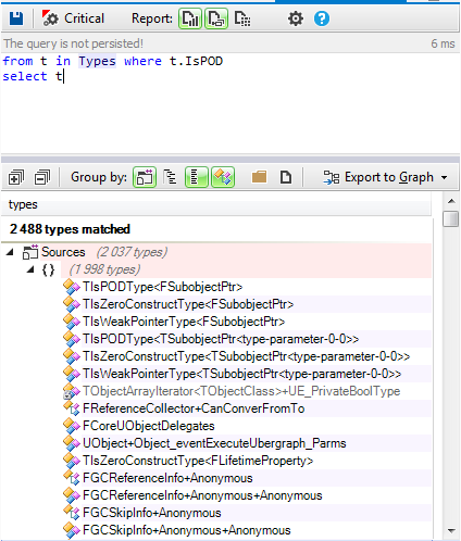
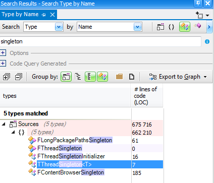

There is one important argument in favor of using immutable objects: It dramatically simplifies concurrent programming. Think about it, why does writing proper multithreaded programming is a hard task? Because it is hard to synchronize threads access to resources (objects or others OS resources). Why it is hard to synchronize these accesses? Because it is hard to guarantee that there won’t be race conditions between the multiple write accesses and read accesses done by multiple threads on multiple objects. What if there are no more write accesses? In other words, what if the state of the objects accessed by threads, doesn’t change? There is no more need for synchronization!

Let's search for classes having at least one base class:

doom6.png

Almost 40% of stucts and classes have a base class. And generally in OOP one of the benefits of inheritance is the polymorphism, here are in blue the virtual methods defined in the source code:

doom7.png

More than 30% of methods are virtual. Few of them are virtual pure and here's the list of all abstract classes defined:

doom9.png

Only 52 are defined abstract classes, 35 of them are defined as pure interfaces,i.e. all their virtual methods are pure.

doom8.png

Let's search for methods using RTTI

doom17.png

Only very few methods use RTTI.

To resume  only basic concepts of OOP are used, no advanced design patterns used, no overuse of interfaces and abstract classes, limited use of RTTI and data are defined as structs.

Until now nothing special differentiate this code from many others using "C with Classes" and criticized by many C++ developers.

Here are some interesting choices of their developers to help us understand its secret:

1 - Provides a common base class with useful services.

Many classes inherits from the idClass:

doom10.png

The idClass  provides the following services:
  1. Instance creation.
  2. Type info management.
  3. Event management.
doom11.png


2- Make easy the string manipulation

Generally the string is the most used type in a project, many treatments are done using them, and we need functions to manipulate them.

Doom3 defines the idstr class which contains almost all useful methods to manipulate strings, no need to define your own method as the case of many string classes provided by other frameworks.

3- The source code is highly decoupled with the GUI framework (MFC)

In many projects using MFC, the code is highly coupled with their types, and you can find types from MFC everywhere in the code.

In Doom3, The code is highly decoupled with MFC, only GUI classes has direct dependency with it. As shown by this following CQLinq query:

doom3.png


This choice has a big impact on the productivity. Indeed, only the Gui developers must care about the MFC framework, and for the other developers it's not mandatory to waste time with MFC.

4- It provides a very good utility library (idlib)

In almost all projects the most used types are utility classes, as shown by the result of this following query:

doom4.png

As we can observe the most used are utilities ones. If  C++ developers don't use a good framework for utilities, they spend most of their developement time to fight with the technical layer.

idlib provides useful classes with all needed methods to treat string, containers, and memory. Which facilitate the work of developers and let them focus more on the game logic.

5- The implementation is very easy to understand

Doom3 implements a hard coded compiler, and as known by C++ developers, it's not an easy task to develop parsers and compilers. However, the implementation of the Doom3 is very easy to understand and its code is very clean.

Here's the dependency graph of the classes used by the compiler:

doom16.png


And here's a code snippet from the compiler source code:

doom15.png

We already study the code source of many parsers and compiler. But it's the first time we discover a compiler with a source code very easy to be understood, it's the same for the whole Doom3 source code. It's magic. When we explore the Doom3 source code, we can't say: WOW it's beautiful!

Summary

Even if the Doom3  design choices are very basic, but its designers make many decisions to let developers focus more on the game logic, and facilitate all the technical layer stuff. Which increase a lot the productivity.

However when using "C with Classes", you have to know exactly what you are doing. You have to be expert like Doom3 developers. It's not recommended for a beginner to take risk and ignore the Modern C++ recommendations.

Creating a Movement Component for an RTS in UE4

$
0
0
My name is Dmitry and I'm a programmer at Snowforged Entertainment. Our team is currently working on Starfall Tactics – an upcoming online RTS game based on the Unreal Engine 4. I’ve just finished refactoring a movement component for spaceships. This component had to be rewritten three times, going back all the way to the start of development on the game to working on the current alpha version.

During this period of time, a lot of mistakes were made and painful lessons learned. In this article, I’d like to share my experience with you and talk about Navigation Volumes, Movement component, AIController and Pawn.

Objective: implement spaceship movement on a given plane.

Things to consider:
  • Spaceships in Starfall Tactics have a maximum speed, rotational speed and a rate of acceleration. These parameters directly influence the ship’s movement.
  • You have to rely on Navigation Volume to automatically search for obstacles and decide on the safest path.
  • There shouldn’t be continuous synchronization of position coordinates across the network.
  • Spaceships can start moving from different speed states.
  • Everything must be done natively with regards to the architecture of Unreal Engine 4.
For the sake of simplicity, I've decided to break up the task into two sub-tasks: searching for the safest/optimal path and moving to the end point (located under the cursor).

Task 1 - Searching for the optimal path


First, let’s consider the elements involved in finding an optimal path via Unreal Engine 4. UShipMovementComponent is a movement component inherited from UPawnMovementComponent, due to the end unit (in this case, our spaceship) being derived from APawn.
UPawnMovementComponent is originated from UNavMovementComponent, which contains the FNavProperties field. These are navigational parameters that describe the shape of a given APawn that is also used by the AIController when searching for pathways.
Suppose we have a level that contains a spaceship, some static objects and Navigation Volume. We decide to send this spaceship from one point of the map to another. This is what happens inside UE4:


scheme41.jpg


1) APawn finds within itself the ShipAIController (in our case, it's just the class that was derived from AIController, having just a single method) and calls the method for seeking pathways.

2) In this method we first prepare a request to the navigation system. Then, after sending the request, we receive movement control points.

TArray<FVector> AShipAIController::SearchPath(const FVector& location)
{
    FPathFindingQuery Query;

    const bool bValidQuery = PreparePathfinding(Query, location, NULL);
    UNavigationSystem* NavSys = UNavigationSystem::GetCurrent(GetWorld());
    FPathFindingResult PathResult;
    TArray<FVector> Result;

    if(NavSys)
    {
        PathResult = NavSys->FindPathSync(Query);

        if(PathResult.Result != ENavigationQueryResult::Error)
        {
            if(PathResult.IsSuccessful() && PathResult.Path.IsValid())
            {
                for(FNavPathPoint point : PathResult.Path->GetPathPoints())
                {
                    Result.Add(point.Location);
                }
            }
        }
        else
        {
            DumpToLog("Pathfinding failed.", true, true, FColor::Red);
        }
    }
    else
    {
        DumpToLog("Can't find navigation system.", true, true, FColor::Red);
    }

    return Result;
}

3) These points are then returned as an array to APawn, in a format that is convenient for us (FVector). Finally, the movement begins.
In a nutshell: APawn contains a ShipAIController, which at the time of the calling of PreparePathfinding() refers to APawn and receives the UShipMovementComponent, containing FNavProperties that address the navigation system in order to find the optimal path.

Task 2 - Implementing movement to the end point


So, we’ve just received a list of movement control points. The first point is always the spaceship’s current position, the latter - our destination. In this case, the place on the game map where we clicked with the cursor.

I should probably tell you a little bit about how we plan to interface with the network. For the sake of simplicity, let’s break up the process into several steps and describe each one:

1) We call the function responsible for starting the movement - AShip::CommandMoveTo():

UCLASS()
class STARFALL_API AShip : public APawn, public ITeamInterface
{
...
    UFUNCTION(BlueprintCallable, Server, Reliable, WithValidation, Category = "Ship")
    void CommandMoveTo(const FVector& location);
    void CommandMoveTo_Implementation(const FVector& location);
    bool CommandMoveTo_Validate(const FVector& location);
...
}

Pay close attention. On the client’s side, all Pawns are missing an AIController, which exists only on the server. So when the client calls the function to send the ship to a new location, all calculations should be done server-side. In other words, the server is responsible for seeking the optimal path for each spaceship because it is the AIController that works with the navigation system.

2) After we’ve found a list of control points inside the CommandMoveTo() method, we call the next one to start moving the selected spaceship. This method should be called on all clients.

UCLASS()
class STARFALL_API AShip : public APawn, public ITeamInterface
{
...
    UFUNCTION(BlueprintCallable, Reliable, NetMulticast, Category = "Ship")
    void StartNavMoveFrom(const FVector& location);
    virtual void StartNavMoveFrom_Implementation(const FVector& location);
...
}

In this method, a client that does not have any control points adds the fist received coordinate to the list of control points and “starts the engine”, moving the ship into motion. Using timers, we activate the process of sending the remaining intermediate and end points for this particular journey on the server:

void AShip::CommandMoveTo(const FVector& location)
{
...
	GetWorldTimerManager().SetTimer(timerHandler,
                                    FTimerDelegate::CreateUObject(this, &AShip::SendNextPathPoint),
                                    0.1f, true);
...

}

UCLASS()
class STARFALL_API AShip : public APawn, public ITeamInterface
{
...
    FTimerHandle timerHandler;
    
    UFUNCTION(BlueprintCallable, Reliable, NetMulticast, Category = "Ship")
    void SendPathPoint(const FVector& location);
    virtual void SendPathPoint_Implementation(const FVector& location);
...
}

On the client’s side, while the ship starts to accelerate and move to the first control point, it gradually receives the remaining control points and adds them to an array. This takes some load off the network and allows us to stretch the time it takes to send data, thus distributing the load.

Alright, enough with the supplementary info. Let’s get back to business ;) Our current task – make the ship move towards the nearest control point. Keep in mind that our ship has rotational speed, as well as a speed of acceleration.

When you send the spaceship to a new destination, it could be flying at full speed, staying still, accelerating or be in the process of turning in that particular moment. Therefore, we have to act depending on current speed characteristics and destination.

We have identified three types of spaceship behavior:


scheme3.png


  1. The vessel can fly to the end point at full speed and fall back on rotational speed to arrive at its destination.
  2. The spaceship’s current speed might be too fast, so it will try to align with its destination using average speed. When the ship directly faces its destination, it will accelerate and try to reach the target at maximum speed.
  3. If the other pathways takes more time than simply rotating on the spot and flying to the target in a straight line, the vessel will proceed to do so.

Before the ship starts moving to a control point, we need to decide on the speed parameters to be used. To achieve this, we’ve implemented a function for simulating a flight. I’d rather skip explaining the code in this article, but if you need more information on this, just drop me a message.

The principles are quite simple - using the current DeltaTime, we keep moving the vector of our position and rotate the forward vector, simulating the vessel’s rotation. It’s quite a simple operation that utilizes vectors and FRotator.

I should probably mention that in each iteration of the ship’s rotation, we should track and accumulate the angle of rotation. If it’s more than 180 degrees, it means that the spaceship has started moving in circles around the end point, so we should probably try the next set of speed parameters.

At first, the spaceship tries to fly at full speed and then at reduced speed (we are currently using average speed). If none of these solutions work – the ship simply needs to rotate in order to align with its destination and fly towards it.

Please keep in mind that all of the logic in the assessment of the situation and the movement processes should be implemented in AShip. This is due to the AIController missing on the client’s side, as well as UShipMovementComponent playing a different role (which I’ll talk about soon). So to make sure that our spaceships can move on their own, without constantly synchronizing coordinates with the server, we need to realize the movement logic within AShip.

Now, let’s talk about the most important part of the whole process - our movement component UShipMovementComponent. You should keep in mind that components of this type are just like engines. Their function is moving the object forward and rotating it when necessary, without worrying about what kind of logic should the object rely on for movement or what state it is in. Once again, they are only responsible for the actual movement of the said subject.

The gist of using UMovementComponent and its derived classes is as follows: we use a given Tick() to make all mathematical calculations related to our component’s parameters (speed, maximum speed, rotational speed). We then set the UMovementComponent::Velocity parameter to a value that is relevant to the spaceship’s transposition at this time tick. Then, we call UMovementComponent::MoveUpdatedComponent(), where the actual transposition and rotation of the spaceship occurs.

void UShipMovementComponent::TickComponent(float DeltaTime, enum ELevelTick TickType,
                                                 FActorComponentTickFunction* ThisTickFunction)
{
    Super::TickComponent(DeltaTime, TickType, ThisTickFunction);

    if(!PawnOwner || !UpdatedComponent || ShouldSkipUpdate(DeltaTime))
    {
        return;
    }

    if (CheckState(EShipMovementState::Accelerating))
    {
        if (CurrentSpeed < CurrentMaxSpeed)
        {
            CurrentSpeed += Acceleration;
            AccelerationPath += CurrentSpeed*DeltaTime;
        }
        else
        {
            CurrentSpeed = CurrentMaxSpeed;
            RemoveState(EShipMovementState::Accelerating);
        }
    }
    else
    if (CheckState(EShipMovementState::Braking))
    {
        if (CurrentSpeed > 0.0f)
        {
            CurrentSpeed -= Acceleration;
            DeaccelerationPath += CurrentSpeed*DeltaTime;
        }
        else
        {
            CurrentSpeed = 0.0f;
            CurrentMaxSpeed = MaxSpeed;

            RemoveState(EShipMovementState::Braking);
            RemoveState(EShipMovementState::Moving);
        }
    }
    else
    if (CheckState(EShipMovementState::SpeedDecreasing))
    {
        if (CurrentSpeed > CurrentMaxSpeed)
        {
            CurrentSpeed -= Acceleration;
            DeaccelerationPath += CurrentSpeed*DeltaTime;
        }
        else
        {
            CurrentSpeed = CurrentMaxSpeed;

            RemoveState(EShipMovementState::SpeedDecreasing);
        }
    }

    if (CheckState(EShipMovementState::Moving) || CheckState(EShipMovementState::Turning))
    {
        MoveForwardWithCurrentSpeed(DeltaTime);
    }
}

...

void UShipMovementComponent::MoveForwardWithCurrentSpeed(float DeltaTime)
{
    Velocity = UpdatedComponent->GetForwardVector() * CurrentSpeed * DeltaTime;

    MoveUpdatedComponent(Velocity, AcceptedRotator, false);
    UpdateComponentVelocity();
}

A few words about the states that appear in this article. They are needed to combine the various processes related to movement. For example, when reducing speed (to have enough space for maneuvering, we need to move at average speed) and rotating towards a new destination.

In the movement component, states are used only for evaluation purposes: should we continue accelerating or should we decrease momentum, etc.

All of the logic related to the transition from one state of motion to another is done via AShip. For example, the spaceship is flying at full speed and the final destination has changed, so we need to lower the vessel’s speed to its average value.

And a quick word about AcceptedRotator. It's the ship’s rotation at the current time tick. In the AShip time tick we call the following method of the UShipMovementComponent:

bool UShipMovementComponent::AcceptTurnToRotator(const FRotator& RotateTo)
{
    if(FMath::Abs(RotateTo.Yaw - UpdatedComponent->GetComponentRotation().Yaw) < 0.1f)
    {
        return true;
    }

    FRotator tmpRot = FMath::RInterpConstantTo(UpdatedComponent->GetComponentRotation(),
                                               RotateTo, GetWorld()->GetDeltaSeconds(),
                                               AngularSpeed);
    AcceptedRotator = tmpRot;

    return false;
}

RotateTo = (GoalLocation - ShipLocation).Rotation() - ie this is a rotator that denotes what rotation value the vessel should be at in order for it to face the end point.

In this method, we evaluate whether the spaceship is already looking at the destination. In that case, this result is returned and the vessel will not rotate. In its assessment of the situation, AShip will reset the state EShipMovementState::Turning - and UShipMovementComponent will no longer attempt to rotate. Otherwise, we use the rotation and interpret based on DeltaTime and the spaceship’s rotational speed. Then apply this rotation to the current time tick, when calling UMovementComponent::MoveUpdatedComponent().

Future Prospects


In my humble opinion, this particular version of UShipMovementComponent takes into account all of the problems our team faced during the prototyping stage of Starfall Tactics. As an added bonus, the solution turned out to be quite scalable and there is an opportunity to improve it further.

Take, for example, the moment when the spaceship is turning: if we simply rotate the ship, it looks dull, as if the vessel is attached to a piece of string. However, allowing the spaceship to dip slightly in the direction of the turn results in an attractive and fluid action.

Also, the synchronization of intermediate spaceship positions is realized on a workable level. As soon as the object reaches its destination, the data is synchronized with the server. So far, the difference in the vessel's final position on the server and the client is fairly small. However, if miscalculations start occurring more frequently, I have a lot of ideas on how to improve synchronization without spaceships performing sudden “jumps”. I guess we’ll talk about them another time.

Creating a Very Simple GUI System for Small Games - Part III

$
0
0
In part one, we familiarized ourselves with positioning and sizes of single GUI parts. Now, its time to render them on the screen. This part is shorter than the previous two, because there is not so much to tell.

You can look at previous chapters:
This time, you will need some kind of an API for main rendering, but doing this is not part of a GUI design. At the end, you don't need to use any sophisticated graphics API at all and you can render your GUI using primitives and bitmaps in your favourite language (Java, C#, etc). Hovewer, what I will be describing next assumes a usage of some graphics API. My samples will be using OpenGL and GLSL, but a change to DirectX should be straightforward.

You have two choices in rendering your GUI. First, you can render everything as a geometry in each frame on top of your scene. Second option is to render the GUI into a texture and then blend this texture with your scene. In most of the cases this will be slower because of the blending part. What is the same for both cases are the rendering elements of your system.

Basic rendering


To keep things as easy as possible we start with the simple approach where each element is rendered separately. This is not a very performance-friendly way if you have a lot of elements, but it will do for now. Plus, in a static GUI used in a main menu and not in an actual game, it can also be a sufficient solution. You may notice warnings in performance utilities that you are rendering too many small primitives. If your framerate is high enough and you don't care about things like power consumption, you can leave things as they are. Power consumption is more likely to be a problem for mobile devices, where a battery lifetime is important. Fewer draw calls can be cheaper and put less strain on your battery; plus your device won't be hot as hell.

In modern APIs, the best way to render things is to use shaders. They offer great user control - you can blend textures with colors, use mask textures to do patterns, etc. We use one shader that can handle every type of element.

The following shader samples are written in GLSL. They use an old version of notation because of a compatibility with OpenGL ES 2.0 (almost every device on the market is using this API). This vertex shader assumes that you have already converted your geometry into the screen space (see first part of the tutorial where [-1, 1] coordinates were mentioned).

attribute vec3 POSITION; 
attribute vec2 TEXCOORD0;

varying vec2 vTexCoord;

void main() 
{			 	
	gl_Position = vec4(POSITION.xyz, 1.0);
	vTexCoord = TEXCOORD0;	 
}

In a pixel (fragment) shader, I am sampling a texture and combining it with color using a simple blending equation. This way, you can create differently colored elements and use some grayscaled texture as a pattern mask.

uniform sampler2D guiElementTexture; 
uniform vec4 guiElementColor;

varying vec2 vTexCoord;

void main() 
{	 
	vec4 texColor = texture2D(guiElementTexture, vTexCoord);      
	vec4 finalColor = (vec4(guiElementColor.rgb, 1) * guiElementColor.a);
	finalColor += (vec4(texColor.rgb, 1) * (1.0 - guiElementColor.a));   
	finalColor.a = texColor.a;      
	gl_FragColor = finalColor; 
}

That is all you need for rendering basic elements of your GUI.

Font rendering

For fonts I have chosen to use this basic renderer instead of an advanced one. If your texts are dynamic (changing very often - score, time), this solution may be faster. The speed of rendering also depends on the text length. For small captions, like “New Game”, “Continue”, “Score: 0” this will be enough. Problems may (and probably will) occur with long texts like tutorials, credits etc. If you will have more than 100 draw-calls in every frame, your frame rate will probably drop down significantly. This is something that can not be told explicitly, it depends on your hardware, driver optimization and other factors. Best way is to try :-) From my experience, there is a major frame drop with rendering 80+ letters, but on the other hand, the screen could be static and the user probably won't notice the difference between 60 and 20 fps.

For classic GUI elements, you have used textures that are changed for every element. For fonts, it would be an overkill and a major slowdown of your application. Of course, in some cases (debug), it may be good to use this brute-force way.

We will use something called a texture atlas instead. That is nothing more then a single texture that holds all possible textures (in our case letters). Look at the picture below if you don't know what I mean :-) Of course, to have only this texture is useless without knowing where each letter is located. This information is usually stored in a separate file that contains coordinate locations for each letter. Second problem is the resolution. Fonts provided and generated by FreeType are created with respect to the font size from vector representations, so they are sharp every time. By using a font texture you may end up with good looking fonts on a small resolutions and blurry ones for a high resolution. You need to find a trade-off between a texture size and your font size. Plus, you must take in mind that most of the GPUs (especially the mobile ones), have a max texture size of 4096x4096. On the other hand, using this resolution for fonts is an overkill. Most of the time I have used 512x512 or 256x256 for rendering fonts with a size 20. It looks good even on Retina iPad.


Attached Image: abeceda.fnt.png
Example of font texture atlas


I have created this texture by myself using the FreeType library and my own atlas creator. There is no support for generating these textures, so you have to write it by yourself. It may sound complicated, but it is not and you can use the same code also for packing other GUI textures. I will give some details of implementation in part IV of the tutorial.

Every font letter is represented by a single quad without the geometry. This quad is created only by its texture coordinates. Position and “real texture coordinates” for the font are passed from the main application and they differ for each letter. I have mentioned “real texture coordinates”. What are they? You have a texture font atlas and those are the coordinates of a letter within this atlas.

In following code samples, a brute-force variant is shown. There is some speed-up, achieved by caching already generated fonts. This can cause problems if you generate too many textures and exceed some of the API limits. For example, if you have long text and render it with several font faces, you can easily generate hunderds of very small textures.

//calculate "scaling"
float sx = 2.0f / screen_width; 	
float sy = 2.0f / screen_height;

//Map texture coordinates from [0, 1] to screen space [-1, 1]
x =  MyMathUtils::MapRange(0, 1, -1, 1, x); 	
y = -MyMathUtils::MapRange(0, 1, -1, 1, y); //-1 is to put origin to bottom left corner of the letter

//wText is UTF-8 since FreeType expect this	 	
for (int i = 0; i < wText.GetLength(); i++) 	
{ 		
	unsigned long c = FT_Get_Char_Index(this->fontFace, wText[i]); 		
	FT_Error error = FT_Load_Glyph(this->fontFace, c, FT_LOAD_RENDER); 	
	if(error) 		
	{ 			
		Logger::LogWarning("Character %c not found.", wText.GetCharAt(i)); 			
		continue; 		
	}
	FT_GlyphSlot glyph = this->fontFace->glyph;

	//build texture name according to letter	
	MyStringAnsi textureName = "Font_Renderer_Texture_"; 
	textureName += this->fontFace;		
	textureName += "_"; 		
	textureName += znak; 	
	if (!MyGraphics::G_TexturePool::GetInstance()->ExistTexture(textureName))
	{
		//upload new letter only if it doesnt exist yet
		//some kind of cache to improve performance :-)
		MyGraphics::G_TexturePool::GetInstance()->AddTexture2D(textureName, //name o texture within pool
				glyph->bitmap.buffer, //buffer with raw texture data
				glyph->bitmap.width * glyph->bitmap.rows, //buffer byte size 				
				MyGraphics::A8,  //only grayscaled texture 				
				glyph->bitmap.width, glyph->bitmap.rows); //width / height of texture		
	} 	
		
	//calculate letter position within screen
	float x2 =  x + glyph->bitmap_left * sx; 		
	float y2 = -y - glyph->bitmap_top  * sy; 
	
	//calculate letter size within screen	
	float w = glyph->bitmap.width * sx; 		
	float h = glyph->bitmap.rows  * sy; 	
		
	this->fontQuad->GetEffect()->SetVector4("cornersData", Vector4(x2, y2, w, h));
	this->fontQuad->GetEffect()->SetVector4("fontColor", fontColor);
	this->fontQuad->GetEffect()->SetTexture("fontTexture", textureName);
	this->fontQuad->Render(); 

    //advance start position to the next letter
	x += (glyph->advance.x >> 6) * sx; 		
	y += (glyph->advance.y >> 6) * sy;
}

To change this code to be able work with a texture atlas is quite easy. What you need to do is use an additional file with coordinates of letters within the atlas. For each letter, those coordinates will be passed along with letter position and size. The texture will be set only once and stay the same until you change the font type. The rest of the code, hovewer, remains the same.

As you can see from code, texture bitmap (glyph->bitmap.buffer) is a part of the glyph provided by FreeType. Even if you don't use it, it is still generated and it takes some time. If your texts are static, you can “cache” them and store everything generated by FreeType during first run (or in some Init step) and then, in runtime, just use precreated variables and don't call any FreeType functions at all. I use this most of the time and there are no performance impacts and problems with font rendering.

Advanced rendering


So far only basic rendering has been presented. Many of you probably knew that, and there was nothing surprising. Well, there will probably be no surprises in this section too.

If you have more elements and want to have them rendered as fast as possible, rendering each of them separately may not be enough. For this reason I have used a “baked” solution. I have created a single geometry buffer, that holds geometry from all elements on the screen and I can draw them with a single draw-call. The problem is that you need to have single shader and elements may be different. For this purpose, I have used a single shader that can handle “everything” and each element has a unified graphics representation. It means that for some elements, you will have unused parts. You may fill those with anything you like, usually zeros. Having this representation with unused parts will end up with a “larger” geometry data. If I have used the word “larger”, think about it. It won't be such a massive overhead and your GUI should still be cheap on memory with a faster drawing. That is the trade-off.

What we need to pass as geometry for every element:
  • POSITION - this will be divided into two parts. XYZ coordinates and W for element index.
  • TEXCOORD0 - two sets of texture coordinates
  • TEXCOORD1 - two sets of texture coordinates
  • TEXCOORD2 - color
  • TEXCOORD3 - additional set of texture coordinates and reserved space to kept padding to vec4
Why do we need different sets of texture coordinates? That is simple. We have baked an entire GUI into one geometry representation. We don't know which texture belongs to which element, plus we have a limited set of textures accessible from a fragment shader. If you put two and two together, you may end up with one solution for textures. Yes, we create another texture atlas built from separate textures for every “baked” element. From what we have already discovered about elements, we know that they can have more than one texture. That is precisely the reason why we have multiple texture coordinates “baked” in a geometry representation. First set is used for the default texture, second for “hovered” textures, next for clicked ones etc. You may choose your own representation.

In a vertex shader we choose the correct texture coordinates according to the element's current state and send coordinates to a fragment shader. Current element state is passed from the main application in an integer array, where each number corresponds to a certain state and -1 for an invisible element (won't be rendered). We don't pass this data every frame but only when the state of an element has been changed. Only then do we update all states for “baked” elements. I have limited the max number of those to be 64 per a single draw-call, but you can decrease or increase this number (be careful with increase, since you may hit the GPU uniforms size limits). Index to this array has been passed as a W component in a POSITION.

The full vertex and the fragment shader can be seen in the following code snipset.

//Vertex buffer content
attribute vec4 POSITION;   //pos (xyz), index (w)
attribute vec4 TEXCOORD0;  //T0 (xy), T1 (zw)
attribute vec4 TEXCOORD1;  //T2 (xy), T3 (zw) 
attribute vec4 TEXCOORD2;  //color 
attribute vec4 TEXCOORD3;  //T4 (xy), unused (zw)

//User provided input
uniform int stateIndex[64]; //64 = max number of elements baked in one buffer

//Output
varying vec2 vTexCoord; 
varying vec4 vColor;

void main() 
{			 	
	gl_Position = vec4(POSITION.xyz, 1.0);       
	int index = stateIndex[int(POSITION.w)];        
	if (index == -1) //not visible 	
	{ 		
		gl_Position = vec4(0,0,0,0); 		
		index = 0; 	
	}      
     
	if (index == 0) vTexCoord = TEXCOORD0.xy; 	
	if (index == 1) vTexCoord = TEXCOORD0.zw; 	
	if (index == 2) vTexCoord = TEXCOORD1.xy; 	
	if (index == 3) vTexCoord = TEXCOORD1.zw;   
	if (index == 4) vTexCoord = TEXCOORD3.xy;            
	vColor = TEXCOORD2;     
}

Note: In vertex shader, you can spot the "ugly" if sequence. If I replaced this code with an if-else, or even a switch, GLSL optimizer for ES version stripped my code somehow and it stopped working. This was the only solution, that worked for me.

varying vec2 vTexCoord; 
varying vec4 vColor;

uniform sampler2D guiBakedTexture;

void main() 
{	
	vec4 texColor = texture2D(guiBakedTexture, vTexCoord);        
	vec4 finalColor = (vec4(vColor.rgb, 1) * vColor.a) + (vec4(texColor.rgb, 1) * (1.0 - vColor.a));  
	finalColor.a = texColor.a;      
	gl_FragColor = finalColor;
}

Conclusion


Rendering GUI is not a complicated thing to do. If you are familiar with basic concepts of rendering and you know how an API works, you will have no problem rendering everything. You need to be careful with text rendering, since there could be significant bottlnecks if you choose the wrong approach.

Next time, in part IV, some tips & tricks will be presented. There will be a simple texture atlas creation, example of user-friendly GUI layout with XML, details regarding touch controls and maybe more :-). The glitch is, that I don't have currently much time, so there could be a longer delay before part IV will see the light of day :-)

Article Update Log


19 May 2014: Initial release

Call Unity3D Methods from Java Plugins using Reflection

$
0
0

Unity is a great game engine to develop mobile games. It brings a lot of functionality with easy to use tools. But as you go deeper in creating Android games with Unity there comes a time when you have to extend Unity by your own Android Java plugins. Unity's documentation is decent enough to get started. Sometimes in your Java code You need to call a Unity method. Unity has a way to do it through UnitySendMessage which is available when you extend UnityPlayerActivity (Or UnityPlayerNativeActivity). But I didn't want to extend UnityPlayerActivity, instead I wanted to write plugins for different jobs and make them useful in other projects too. I wanted to have several plugins for different jobs and seperated from each other so extending UnityPlayerActivity was not a good choice. By the way, you may have 3rd-party plugins that already extend UnityPlayerActivity. In this article you will learn how to do it in this way (not extending UnityPlayerActivity)


NOTE: I suppose you know already how to create a Java plugin for unity. If you don't please see Unity's Documentation.

Unity Part


In Unity you have to prepare a GameObject with a name. In this article I use the default GameObject that you have when you create a new scene in Unity, Main Camera. Rename "Main Camera" to "MainCamera" (We will use this name in Java to call a Unity Method in the future). Then write a script that contains a public method which receives a string as input and returns nothing (void) This is the method that's going to be called. Its name is also important because it is also used in Java code. maybe some method like this:

public void OnJavaCall(string message)
{
    Debug.Log(message);
}

I kept it as simple as possible, the method just logs the message. Attach the script that you just wrote to the MainCamera.

The Java Part


In your Java code you can now call the method (OnJavaCall in this example). You have to write out code similar to what's shown below:

public static void CallUnityFunc(Activity activity)
	{
		Log.i(Tag, "Calling unity function");
		
		
		try 
		{
			
			Field UnityPlayer = activity.getClass().getDeclaredField("mUnityPlayer");
			
			UnityPlayer.setAccessible(true);
			
			Method method = UnityPlayer.getType().getDeclaredMethod("UnitySendMessage", String.class,String.class,String.class);
            
			method.setAccessible(true);
			method.invoke(activity, "MainCamera","OnJavaCall","Hello Unity , From Java");

			
		} 
		catch(Exception e)
		{
			Log.e(Tag,e.getClass().toString()+"  "+ e.getMessage());
		}
		
	}

I wrote a static method that takes an Activity as input. We will pass the Unity player to this Method in the future. In the method declaration as you can see I use reflection to call the UnitySendMessage. UnitySendMessage takes three parameters : The GameObject's name (MainCamera in this example), Method's name (OnJavaCall here), and The message that is going to be sent as an arguement to our method (OnJavaCall).

To test it now you have to compile your plugin (which is an Android library project) to generate a .jar file. After that you know of course you have to copy the .jar file to your Unity project.

Back to Unity


Then in Unity, call that static method (CallUnityFunc here) we wrote in Java to see how it works. for example:

AndroidJavaClass classPlayer = new AndroidJavaClass("com.unity3d.player.UnityPlayer");
AndroidJavaObject activity = classPlayer.GetStatic<AndroidJavaObject>("currentActivity");

AndroidJavaClass PluginClass = new AndroidJavaClass("com.helper.bazaarpayment.PluginClass");// put your own package and class name accordingly to your Java plugin

//so let's call it 
PluginClass.CallStatic("CallUnityFunc",activity);

Note that this code will not work untill you actually run it on an Android device. It's good to check for runtime platform through Application.platform.

Note that when you make this call to Java, The MainCamera (containing the script that has OnJavaCall) that we created must be present, otherwise there won't be any GameObject with name MainCamera that has a OnJavaCall method. You may want to use GameObject.DontDestroyOnLoad to ensure you have MainCamera in all places.

Compile and run to see how it works. You can use the adb interface located at platform-tools folder in your Android sdk folder. With command: adb logcat -s Unity you can see Unity logs.

With this approach you don't have to extend UnityPlayerActivity. You can have self-contained plugins for distinct tasks. You can also leave 3rd-party plugins that extend UnityPlayerActivity to work untouched.

Creating a Very Simple GUI System for Small Games - Part III

$
0
0
In part one, we familiarized ourselves with positioning and sizes of single GUI parts. Now, its time to render them on the screen. This part is shorter than the previous two, because there is not so much to tell.

You can look at previous chapters:
This time, you will need some kind of an API for main rendering, but doing this is not part of a GUI design. At the end, you don't need to use any sophisticated graphics API at all and you can render your GUI using primitives and bitmaps in your favourite language (Java, C#, etc). Hovewer, what I will be describing next assumes a usage of some graphics API. My samples will be using OpenGL and GLSL, but a change to DirectX should be straightforward.

You have two choices in rendering your GUI. First, you can render everything as a geometry in each frame on top of your scene. Second option is to render the GUI into a texture and then blend this texture with your scene. In most of the cases this will be slower because of the blending part. What is the same for both cases are the rendering elements of your system.

Basic rendering


To keep things as easy as possible we start with the simple approach where each element is rendered separately. This is not a very performance-friendly way if you have a lot of elements, but it will do for now. Plus, in a static GUI used in a main menu and not in an actual game, it can also be a sufficient solution. You may notice warnings in performance utilities that you are rendering too many small primitives. If your framerate is high enough and you don't care about things like power consumption, you can leave things as they are. Power consumption is more likely to be a problem for mobile devices, where a battery lifetime is important. Fewer draw calls can be cheaper and put less strain on your battery; plus your device won't be hot as hell.

In modern APIs, the best way to render things is to use shaders. They offer great user control - you can blend textures with colors, use mask textures to do patterns, etc. We use one shader that can handle every type of element.

The following shader samples are written in GLSL. They use an old version of notation because of a compatibility with OpenGL ES 2.0 (almost every device on the market is using this API). This vertex shader assumes that you have already converted your geometry into the screen space (see first part of the tutorial where [-1, 1] coordinates were mentioned).

attribute vec3 POSITION; 
attribute vec2 TEXCOORD0;

varying vec2 vTexCoord;

void main() 
{			 	
	gl_Position = vec4(POSITION.xyz, 1.0);
	vTexCoord = TEXCOORD0;	 
}

In a pixel (fragment) shader, I am sampling a texture and combining it with color using a simple blending equation. This way, you can create differently colored elements and use some grayscaled texture as a pattern mask.

uniform sampler2D guiElementTexture; 
uniform vec4 guiElementColor;

varying vec2 vTexCoord;

void main() 
{	 
	vec4 texColor = texture2D(guiElementTexture, vTexCoord);      
	vec4 finalColor = (vec4(guiElementColor.rgb, 1) * guiElementColor.a);
	finalColor += (vec4(texColor.rgb, 1) * (1.0 - guiElementColor.a));   
	finalColor.a = texColor.a;      
	gl_FragColor = finalColor; 
}

That is all you need for rendering basic elements of your GUI.

Font rendering

For fonts I have chosen to use this basic renderer instead of an advanced one. If your texts are dynamic (changing very often - score, time), this solution may be faster. The speed of rendering also depends on the text length. For small captions, like “New Game”, “Continue”, “Score: 0” this will be enough. Problems may (and probably will) occur with long texts like tutorials, credits etc. If you will have more than 100 draw-calls in every frame, your frame rate will probably drop down significantly. This is something that can not be told explicitly, it depends on your hardware, driver optimization and other factors. Best way is to try :-) From my experience, there is a major frame drop with rendering 80+ letters, but on the other hand, the screen could be static and the user probably won't notice the difference between 60 and 20 fps.

For classic GUI elements, you have used textures that are changed for every element. For fonts, it would be an overkill and a major slowdown of your application. Of course, in some cases (debug), it may be good to use this brute-force way.

We will use something called a texture atlas instead. That is nothing more then a single texture that holds all possible textures (in our case letters). Look at the picture below if you don't know what I mean :-) Of course, to have only this texture is useless without knowing where each letter is located. This information is usually stored in a separate file that contains coordinate locations for each letter. Second problem is the resolution. Fonts provided and generated by FreeType are created with respect to the font size from vector representations, so they are sharp every time. By using a font texture you may end up with good looking fonts on a small resolutions and blurry ones for a high resolution. You need to find a trade-off between a texture size and your font size. Plus, you must take in mind that most of the GPUs (especially the mobile ones), have a max texture size of 4096x4096. On the other hand, using this resolution for fonts is an overkill. Most of the time I have used 512x512 or 256x256 for rendering fonts with a size 20. It looks good even on Retina iPad.


Attached Image: abeceda.fnt.png
Example of font texture atlas


I have created this texture by myself using the FreeType library and my own atlas creator. There is no support for generating these textures, so you have to write it by yourself. It may sound complicated, but it is not and you can use the same code also for packing other GUI textures. I will give some details of implementation in part IV of the tutorial.

Every font letter is represented by a single quad without the geometry. This quad is created only by its texture coordinates. Position and “real texture coordinates” for the font are passed from the main application and they differ for each letter. I have mentioned “real texture coordinates”. What are they? You have a texture font atlas and those are the coordinates of a letter within this atlas.

In following code samples, a brute-force variant is shown. There is some speed-up, achieved by caching already generated fonts. This can cause problems if you generate too many textures and exceed some of the API limits. For example, if you have long text and render it with several font faces, you can easily generate hunderds of very small textures.

//calculate "scaling"
float sx = 2.0f / screen_width; 	
float sy = 2.0f / screen_height;

//Map texture coordinates from [0, 1] to screen space [-1, 1]
x =  MyMathUtils::MapRange(0, 1, -1, 1, x); 	
y = -MyMathUtils::MapRange(0, 1, -1, 1, y); //-1 is to put origin to bottom left corner of the letter

//wText is UTF-8 since FreeType expect this	 	
for (int i = 0; i < wText.GetLength(); i++) 	
{ 		
	unsigned long c = FT_Get_Char_Index(this->fontFace, wText[i]); 		
	FT_Error error = FT_Load_Glyph(this->fontFace, c, FT_LOAD_RENDER); 	
	if(error) 		
	{ 			
		Logger::LogWarning("Character %c not found.", wText.GetCharAt(i)); 			
		continue; 		
	}
	FT_GlyphSlot glyph = this->fontFace->glyph;

	//build texture name according to letter	
	MyStringAnsi textureName = "Font_Renderer_Texture_"; 
	textureName += this->fontFace;		
	textureName += "_"; 		
	textureName += znak; 	
	if (!MyGraphics::G_TexturePool::GetInstance()->ExistTexture(textureName))
	{
		//upload new letter only if it doesnt exist yet
		//some kind of cache to improve performance :-)
		MyGraphics::G_TexturePool::GetInstance()->AddTexture2D(textureName, //name o texture within pool
				glyph->bitmap.buffer, //buffer with raw texture data
				glyph->bitmap.width * glyph->bitmap.rows, //buffer byte size 				
				MyGraphics::A8,  //only grayscaled texture 				
				glyph->bitmap.width, glyph->bitmap.rows); //width / height of texture		
	} 	
		
	//calculate letter position within screen
	float x2 =  x + glyph->bitmap_left * sx; 		
	float y2 = -y - glyph->bitmap_top  * sy; 
	
	//calculate letter size within screen	
	float w = glyph->bitmap.width * sx; 		
	float h = glyph->bitmap.rows  * sy; 	
		
	this->fontQuad->GetEffect()->SetVector4("cornersData", Vector4(x2, y2, w, h));
	this->fontQuad->GetEffect()->SetVector4("fontColor", fontColor);
	this->fontQuad->GetEffect()->SetTexture("fontTexture", textureName);
	this->fontQuad->Render(); 

    //advance start position to the next letter
	x += (glyph->advance.x >> 6) * sx; 		
	y += (glyph->advance.y >> 6) * sy;
}

To change this code to be able work with a texture atlas is quite easy. What you need to do is use an additional file with coordinates of letters within the atlas. For each letter, those coordinates will be passed along with letter position and size. The texture will be set only once and stay the same until you change the font type. The rest of the code, hovewer, remains the same.

As you can see from code, texture bitmap (glyph->bitmap.buffer) is a part of the glyph provided by FreeType. Even if you don't use it, it is still generated and it takes some time. If your texts are static, you can “cache” them and store everything generated by FreeType during first run (or in some Init step) and then, in runtime, just use precreated variables and don't call any FreeType functions at all. I use this most of the time and there are no performance impacts and problems with font rendering.

Advanced rendering


So far only basic rendering has been presented. Many of you probably knew that, and there was nothing surprising. Well, there will probably be no surprises in this section too.

If you have more elements and want to have them rendered as fast as possible, rendering each of them separately may not be enough. For this reason I have used a “baked” solution. I have created a single geometry buffer, that holds geometry from all elements on the screen and I can draw them with a single draw-call. The problem is that you need to have single shader and elements may be different. For this purpose, I have used a single shader that can handle “everything” and each element has a unified graphics representation. It means that for some elements, you will have unused parts. You may fill those with anything you like, usually zeros. Having this representation with unused parts will end up with a “larger” geometry data. If I have used the word “larger”, think about it. It won't be such a massive overhead and your GUI should still be cheap on memory with a faster drawing. That is the trade-off.

What we need to pass as geometry for every element:
  • POSITION - this will be divided into two parts. XYZ coordinates and W for element index.
  • TEXCOORD0 - two sets of texture coordinates
  • TEXCOORD1 - two sets of texture coordinates
  • TEXCOORD2 - color
  • TEXCOORD3 - additional set of texture coordinates and reserved space to kept padding to vec4
Why do we need different sets of texture coordinates? That is simple. We have baked an entire GUI into one geometry representation. We don't know which texture belongs to which element, plus we have a limited set of textures accessible from a fragment shader. If you put two and two together, you may end up with one solution for textures. Yes, we create another texture atlas built from separate textures for every “baked” element. From what we have already discovered about elements, we know that they can have more than one texture. That is precisely the reason why we have multiple texture coordinates “baked” in a geometry representation. First set is used for the default texture, second for “hovered” textures, next for clicked ones etc. You may choose your own representation.

In a vertex shader we choose the correct texture coordinates according to the element's current state and send coordinates to a fragment shader. Current element state is passed from the main application in an integer array, where each number corresponds to a certain state and -1 for an invisible element (won't be rendered). We don't pass this data every frame but only when the state of an element has been changed. Only then do we update all states for “baked” elements. I have limited the max number of those to be 64 per a single draw-call, but you can decrease or increase this number (be careful with increase, since you may hit the GPU uniforms size limits). Index to this array has been passed as a W component in a POSITION.

The full vertex and the fragment shader can be seen in the following code snipset.

//Vertex buffer content
attribute vec4 POSITION;   //pos (xyz), index (w)
attribute vec4 TEXCOORD0;  //T0 (xy), T1 (zw)
attribute vec4 TEXCOORD1;  //T2 (xy), T3 (zw) 
attribute vec4 TEXCOORD2;  //color 
attribute vec4 TEXCOORD3;  //T4 (xy), unused (zw)

//User provided input
uniform int stateIndex[64]; //64 = max number of elements baked in one buffer

//Output
varying vec2 vTexCoord; 
varying vec4 vColor;

void main() 
{			 	
	gl_Position = vec4(POSITION.xyz, 1.0);       
	int index = stateIndex[int(POSITION.w)];        
	if (index == -1) //not visible 	
	{ 		
		gl_Position = vec4(0,0,0,0); 		
		index = 0; 	
	}      
     
	if (index == 0) vTexCoord = TEXCOORD0.xy; 	
	if (index == 1) vTexCoord = TEXCOORD0.zw; 	
	if (index == 2) vTexCoord = TEXCOORD1.xy; 	
	if (index == 3) vTexCoord = TEXCOORD1.zw;   
	if (index == 4) vTexCoord = TEXCOORD3.xy;            
	vColor = TEXCOORD2;     
}

Note: In vertex shader, you can spot the "ugly" if sequence. If I replaced this code with an if-else, or even a switch, GLSL optimizer for ES version stripped my code somehow and it stopped working. This was the only solution, that worked for me.

varying vec2 vTexCoord; 
varying vec4 vColor;

uniform sampler2D guiBakedTexture;

void main() 
{	
	vec4 texColor = texture2D(guiBakedTexture, vTexCoord);        
	vec4 finalColor = (vec4(vColor.rgb, 1) * vColor.a) + (vec4(texColor.rgb, 1) * (1.0 - vColor.a));  
	finalColor.a = texColor.a;      
	gl_FragColor = finalColor;
}

Conclusion


Rendering GUI is not a complicated thing to do. If you are familiar with basic concepts of rendering and you know how an API works, you will have no problem rendering everything. You need to be careful with text rendering, since there could be significant bottlnecks if you choose the wrong approach.

Next time, in part IV, some tips & tricks will be presented. There will be a simple texture atlas creation, example of user-friendly GUI layout with XML, details regarding touch controls and maybe more :-). The glitch is, that I don't have currently much time, so there could be a longer delay before part IV will see the light of day :-)

Article Update Log


19 May 2014: Initial release

XRay Unreal Engine 4.5 source code

$
0
0
The Unreal Engine is a game engine developed by Epic Games, first showcased in the 1998 first-person shooter game Unreal. Although primarily developed for first-person shooters, it has been successfully used in a variety of other genres, including stealth, MMORPGs, and other RPGs.

Its code is written in C++ and it's used by many game developers today. Its source code is available for free from GitHub. Many amazing games were developed using this engine, it permits developers to produce very realistic renderings like this one.

488-unreal-engine-4.jpg

What's the source code executed behind the scene to produce this realistic rendering?

It's very interesting to go inside this powerful game engine and discover how it's designed and implemented. C++ developers could learn many good practices from its code base.

Let's XRay its source code using CppDepend and CQLinq to explore some design and implementation choices of its developement team.

1- Namespaces


Unreal Engine uses namespaces widely for three main reasons:
  • Many namespaces contain only enums as shown by this following CQLinq query, which gives us the ones containing only enums.
unreal2.png

In a large project, you would not be guaranteed that two distinct enums don't both get called with the same name. This issue was resolved in C++11, using enum class which implicitly scope the enum values within the enum's name.
  • Anonymous namespace: Namespace with no name avoids making global static variable. The “anonymous” namespace you have created will only be accessible within the file you created it in. Here it is the list of all anonymous namespaces used:
unreal3.png
  • Modularizing the code base: Let's search for all the other namespaces, i.e. neither the anonymous ones nor the ones containing only enums:
unreal6.png

The namespaces represent a good solution to modularize the application; Unreal Engine defines more than 250 namespaces to enforces its modularity, which makes the code more readable and maintainable.

2- Paradigm used


C++ is not just an object-oriented language. As Bjarne Stroustrup points out, “C++ is a multi-paradigmed language.” It supports many different styles of programs, or paradigms, and object-oriented programming is only one of these. Some of the others are procedural programming and generic programming.


2-1 Procedural Paradigm


2-1-1 Global functions


Let’s search for all global functions defined in the Unreal Engine source code:


unreal7.png

We can classify these functions in three categories:


1 - Utility functions: For example 6344 of them concern Z_Construct_UXXX functions, which are used to create instances needed by the engine.


unreal8.png


2 - Operators: Many operators are defined as it is shown, by the result of this CQLinq query:


unreal9.png


Almost all kinds of operators are implemented in the Unreal Engine source code.


3 - Functions related to the engine logic: Many global functions containing some engine treatments are implemented. Maybe these kinds of functions could be grouped by category, as static methods into classes, or grouped in namespaces.


2-1-2 Static global functions:


It's a best practice to declare a global function as static unless you have a specific need to call it from another source file.


unreal10.png


Many global functions are declared as static, and as specified before, other global functions are defined inside anonymous namespaces


2-1-3 Global functions candidate to be static.


Global not exported functions, not defined in an anonymous namespace and not used by any method outside the file where they were defined. These are good candidates to be refactored to be static.


unreal65.png


As we can observe some global functions are candidates to be refactored to be static.


2-2 Object Oriented paradigm


2-2-1 Inheritance


In object-oriented programming (OOP), inheritance is a way to establish Is-a relationship between objects. It is often confused as a way to reuse the existing code which is not a good practice because inheritance for implementation reuse leads to Tight Coupling. Re-usability of code is achieved through composition (Composition over inheritance). Let’s search for all classes having at least one base class:

unreal13.png


And to have a better idea of the classes concerned by this query, we can use the Metric View.


In the Metric View, the code base is represented through a Treemap. Treemapping is a method for displaying tree-structured data by using nested rectangles. The tree structure used in a CppDepend treemap is the usual code hierarchy:

  • Projects contain namespaces.
  • Namespaces contain types.
  • Types contain methods and fields.

The treemap view provides a useful way to represent the result of a CQLinq request; the blue rectangles represent this result, so we can visually see the types concerned by the request.


unreal12.png


As we can observe, the inheritance is widely used in the Unreal Engine source code.


Multiple Inheritance: Let's search for classes inheriting from more than one concrete class.


unreal15.png


The multiple inheritance is not widely used, only a few classes inherit from more than one class.


2-2-2 Virtual methods


Let's search for all virtual methods defined in the Unreal Engine source code:


unreal19.png


Many methods are virtual, and some of them are pure virtual:


unreal21.png


As with the procedural paradigm, the OOP paradigm is also widely used in the Unreal Engine source code. What about the generic programming paradigm?


2-3 Generic Programming


C++ provides unique abilities to express the ideas of Generic Programming through templates. Templates provide a form of parametric polymorphism that allows the expression of generic algorithms and data structures. The instantiation mechanism of C++ templates insures that when a generic algorithm or data structure is used, a fully-optimized and specialized version will be created and tailored for that particular use, allowing generic algorithms to be as efficient as their non-generic counterparts.


2-3-1 Generic types:


Let's search for all genric types defined in the engine source code:


unreal23.png


Only a few types are defined as generic. Let's search for generic methods:


unreal26.png


More than 40000 methods are generic; they represent more than 25% of the methods implemented.

To resume the Unreal Engine source code, mix between the three paradigms.

3- PODs to define the data model


In object-oriented programming, plain old data (POD) is a data structure that is represented only as passive collections of field values (instance variables), without using object-oriented features. In computer science, this is known as passive data structure

Let's search for the POD types in the Unreal Engine source code

unreal28.png

More than 2000 types are defined as POD types, many of them are used to define the engine data model.

4- Gang Of Four design patterns


Design Patterns are a software engineering concept describing recurring solutions to common problems in software design. Gang of four patterns are the most popular ones. Let's discover some of them used in the Unreal Engine source code.

4-1 Singleton

The singleton is the most popular and the most used one. Here are some singleton classes defined in the source code:

unreal29.png

TThreadSingleton is a special version of singleton. It means that there is created only one instance for each thread. Calling its method Get() is thread-safe.

4-2 Factory

Using factory is interesting to isolate the logic instantiation and enforces the cohesion; here is the list of factories defined in the source code:

unreal30.png

And here's the list of the abstract ones:

unreal31.png

4-3 Observer

The observer pattern is a software design pattern in which an object maintains a list of its dependents, called observers, and notifies them automatically of any state changes, usually by calling one of their methods.

They are some observers implemented in its source code, FAIMessageObserver is one of them.

Here's a dependency graph to show the call of the OnMessage method of this observer:

unreal70.png

4-4 Command

The command pattern is a behavioral design pattern in which an object is used to represent and encapsulate all the information needed to call a method at a later time.

Four terms always associated with the command pattern are command, receiver, invoker and client. A command object has a receiver object and invokes a method of the receiver in a way that is specific to that receiver's class.

Here's for example all commands inheriting from the IAutomationLatentCommand:

unreal33.png

5- Coupling and Cohesion


5-1 Coupling

Low coupling is desirable because a change in one area of an application will require fewer changes throughout the entire application. In the long run, this could alleviate a lot of time, effort, and cost associated with modifying and adding new features to an application.


Low coupling could be acheived by using abstract classes or using generic types and methods.


Let’s search for all abstract classes defined in the Unreal Engine source code :


unreal34.png

Only a few types are declared as abstract. The low coupling is more enforced by using generic types and generic methods.

Here's for example the methods using at least one generic method:

unreal27.png

As we can observe many methods use the generic ones, the low coupling is enforced by the function template params. Indeed the real type of these parameters could change without changing the source code of the method called.

5-2 Cohesion

The single responsibility principle states that a class should not have more than one reason to change. Such a class is said to be cohesive. A high LCOM value generally pinpoints a poorly cohesive class. There are several LCOM metrics. The LCOM takes its values in the range [0-1]. The LCOM HS (HS stands for Henderson-Sellers) takes its values in the range [0-2]. A LCOM HS value higher than 1 should be considered alarming. Here are how to compute LCOM metrics:

LCOM = 1 – (sum(MF)/M*F)
LCOM HS = (M – sum(MF)/F)(M-1)

Where:

  • M is the number of methods in class (both static and instance methods are counted, it includes also constructors, properties getters/setters, events add/remove methods).
  • F is the number of instance fields in the class.
  • MF is the number of methods of the class accessing a particular instance field.
  • Sum(MF) is the sum of MF over all instance fields of the class.

The underlying idea behind these formulas can be stated as follows: a class is utterly cohesive if all its methods use all its methods use all its instance fields, which means that sum(MF)=M*F and then LCOM = 0 and LCOMHS = 0.


LCOMHS values higher than 1 should be considered alarming.


unreal36.png


Only some types are considered as not cohesive.


6- Immutability, Purity and side effect


6-1 Immutable types

Basically, an object is immutable if its state doesn’t change once the object has been created. Consequently, a class is immutable if its instances are immutable.


There is one important argument in favor of using immutable objects: It dramatically simplifies concurrent programming. Think about it, why is writing proper multithreaded programming a hard task? Because it is hard to synchronize threads access to resources (objects or others OS resources). Why is it hard to synchronize these accesses? Because it is hard to guarantee that there won’t be race conditions between the multiple write accesses and read accesses done by multiple threads on multiple objects. What if there are no more write accesses? In other words, what if the state of the objects accessed by threads, doesn’t change? There is no more need for synchronization!


Another benefit of immutable classes is that they can never violate LSP (Liskov Subtitution Principle) , here’s a definition of LSP quoted from its wiki page:
Liskov’s notion of a behavioral subtype defines a notion of substitutability for mutable objects; that is, if S is a subtype of T, then objects of type T in a program may be replaced with objects of type S without altering any of the desirable properties of that program (e.g., correctness).

Here's the list of immutable types defined in the source code:

unreal38.png

6-2 purity and side effect

The primary benefit of immutable types come from the fact that they eliminate side-effects. I couldn’t say it better than Wes Dyer so I quote him:

We all know that generally it is not a good idea to use global variables. This is basically the extreme of exposing side-effects (the global scope). Many of the programmers who don’t use global variables don’t realize that the same principles apply to fields, properties, parameters, and variables on a more limited scale: don’t mutate them unless you have a good reason.(…)

One way to increase the reliability of a unit is to eliminate the side-effects. This makes composing and integrating units together much easier and more robust. Since they are side-effect free, they always work the same no matter the environment. This is called referential transparency.

Writing your functions/methods without side effects - so they're pure functions, i.e. not mutate the object - makes it easier to reason about the correctness of your program.

Here's the list of all methods without side-effects

unreal41.png

More than 125 000 methods are pure.

7- Implementation quality


7-1 Too big methods


Methods with many number of lines of code are not easy to maintain and understand. Let’s search for methods with more than 60 lines.


unreal44.png


Unreal Engine source code contains more than 150 000 methods, so less than 1% could be considered as too big.


7-2 Methods with many parameters


unreal45.png


Few methods have more than 8 parameters, most of them are generic, to avoid defining variadic functions, like the case of TCStringt::Snprintf methods.


7-3 Methods with many local variables


unreal46.png


Less than 1% have many local variables.


7-4 Methods too complex


Many metrics exist to detect complex functions, NBLinesOfCode, Number of parameters and number of local variables are the basic ones.


There are other interesting metrics to detect complex functions:

  • Cyclomatic complexity is a popular procedural software metric equal to the number of decisions that can be taken in a procedure.
  • Nesting Depth is a metric defined on methods that is relative to the maximum depth of the more nested scope in a method body.
  • Max Nested loop is equals the maximum level of loop nesting in a function.

The max value tolerated for these metrics depends more on the team choices, there are no standard values.


Let’s search for methods that could be considered as complex in the Unreal Engine code base.


unreal49.png


Only 1.5% are candidate to be refactored to minimize their complexity.


7-4 Halstead complexity

Halstead complexity measures are software metrics introduced by Maurice Howard Halstead in 1977. Halstead made the observation that metrics of the software should reflect the implementation or expression of algorithms in different languages, but be independent of their execution on a specific platform. These metrics are therefore computed statically from the code.

Many metrics were introduced by Halstead, let's take as example the TimeToImplement one, which represents the time required to program a method in seconds.

unreal50.png

1748 methods require more than one hour to be implemented.

8- RTTI


RTTI refers to the ability of the system to report on the dynamic type of an object and to provide information about that type at runtime (as opposed to at compile time). However, RTTI has become controversial within the C++ community. Many C++ developers choose to not use this mechanism.

What about Unreal Engine developers team?

unreal60.png

No method uses the dynamic_cast keyword, The Unreal Engine team chose to not use the RTTI mechanism.

9- Exceptions


Exception handling is also another controversial C++ feature. Many known open source C++ projects do not use it.

Let's search whether in the Unreal Engine source code an exception was thrown.

unreal62.png

Exceptions are thrown in some methods; let's take as example the RaiseException one:

unreal61.png

As specified in their comments, the exception could be generated for the header tool, but in normal runtime code they don't support exception handling.

10- Some final statistics


10-1 most popular types

It’s interesting to know the most used types in a project; indeed these types must be well designed, implemented and tested. And any change occuring to them could impact the whole project.

We can find them using the TypesUsingMe metric:

unreal71.png

However there's another interesting metric to search for popular types: TypeRank.

TypeRank values are computed by applying the Google PageRank algorithm on the graph of types’ dependencies. A homothety of center 0.15 is applied to make it so that the average of TypeRank is 1.

Types with high TypeRank should be more carefully tested because bugs in such types will likely be more catastrophic.

Here’s the result of all popular types according to the TypeRank metric:

unreal52.png

10-2 Most popular methods

unreal54.png

10-3 Methods calling many other methods

It’s interesting to know the methods using many other ones, It could reveal a design problem in these methods. And in some cases a refactoring is needed to make them more readable and maintainable.

unreal57.png

Improve Player Retention Reacting to Behavior [Server Scripts]

$
0
0
Picture this. After you’ve fought hard to release your game and you’re lucky enough to get a pretty decent number of users downloading your game, they get tangled up in Level #8 and can’t manage to get past it.

According to your analytics service, they seemed to be enjoying the game so far, but now the users are logging in at a lower rate. You’re losing active users. What’s going on?

There’s no question they like your game. Why would they play up to Level #8 if they didn’t? The thing is maybe you overestimated the user's ability to reach enough proficiency in the game to advance to further levels. Level #8 might be too difficult for most users and that’s why they are no longer logging in to the game. Thus, you’re losing users.

There are many solutions to the problem. You could reduce the number of enemy waves, add player stamina, change the timing of the game or add more game levels before they get to Level #8, allowing users to be more game-savvy by then.

You do what you have to do


Ok, you decide to modify the game’s parameters to ease it on your users so they keep on enjoying the game and choose to stay. Say you’re a programming beast and that you’re able to swiftly adjust the code and successfully test the game mechanics in one day. That’s good and all but you still need Google Play or the App Store to approve it and publish it - a day for the former and a whopping 7 days for the latter.

The lack of control over the response time for the in-game modifications hampers your ability to make the game progress. I don’t want to be a bummer, but you’re still losing users.

Having passed the period of time for the changes to go live - which seemed longer than you care to admit - users still have to accept to download the latest version of the game. Some of them do it right away, some might do it at a later time… or never at all. After all that rush to get the newest version active, it is still up to your game users having the latest version if you want to see whether the fixes have a positive effect.

Right, you continue losing users.

It’s really hard to get good feedback from the users - and react accordingly - when not all of them are running the latest version.


water-slide.jpg


You can turn it around


The use of external servers to store game mechanics data is a rapidly increasing tendency among game developers. Offering flexibility and a quick response is key to be adaptable to the needs of your users. Imagine a service that cuts your response time to a minimum, gives uninterrupted game play to your users and lets you test different approaches at the same time.

Why store parameters in an external server


#1 Never let others dictate your response time

Your response time shouldn’t be much longer than what you spend on tweaking your code. Fixing it to have the changes go live barely at the same time, you’ll be able to deliver a quicker response to your users’ needs and keep them engaged. Getting user data faster allows you to decide if the changes came to effect or if you need another iteration of changes.

#2 Don’t annoy users with a game update download

Having your users experience the updated game on-the-go releases their need to download any game updates manually. They’ll always play the latest version of the game so you’ll get very reliable user data because there won’t be different versions running at the same time.

#3 Find solutions on-the-go

Upload different solutions to the same problem to simultaneously test which one performs better among users. Split testing subtle code differences will return twice as many data, which means reducing the time you spend to find the best adjustments for the game.

Server side scripts allow maximum configurability


Take this as an example. You could create a config collection in the server side to keep a simple config JSON. This would be the code for it.

{
"levels":
{
"1": { "difficulty": 1, "time": 60 },
"2": { "difficulty": 3, "time": 70 },
"3": { "difficulty": 5, "time": 80 },
"4": { "difficulty": 7, "time": 90 },
"5": { "difficulty": 9, "time": 100 },
},
"adsplatform": "iads",
"coinseveryday":
{ "1": 10, "2": 20, "3":30, "4": 60, "5": 100 }
}

Every time a user opens a new game session you can check if this config has been changed or not. If it has, it’ll start the download of the new game’s config and will start using them right away.

Besides, you can also implement A/B testing with one custom script very easily.
  • Create two or three JSON config samples in the collection.
  • Define a custom script - new server function - called getGameParameters.
  • Call this function every time a user logs in to your game.
This function will be a simple Javascript - using a round robin technique - that will decide what JSON has to be sent: A, B or C. This way the decision point is on server side, can be easily changed and you will be able to test different simultaneous configurations to get better results.

Now you know you can improve user experience storing game mechanics in the server side, what other situations do you think you could use this for your game?

I'd like to know! Leave a comment.


This was originally posted in Gamedonia blog.

Pathfinding and Local Avoidance for RPG/RTS Games using Unity

$
0
0

If you are making an RPG or RTS game, chances are that you will need to use some kind of pathfinding and/or local avoidance solution for the behaviour of the mobs. They will need to get around obstacles, avoid each other, find the shortest path to their target and properly surround it. They also need to do all of this without bouncing around, getting stuck in random places and behave as any good crowd of cows would:


tutorial_00.jpg

In this blog post I want to share my experience on how to achieve a result that is by no means perfect, but still really good, even for release. We'll talk about why I chose to use Unity's built in NavMesh system over other solutions and we will create an example scene, step by step. I will also show you a couple of tricks that I learned while doing this for my game. With all of that out of the way, let's get going.


Choosing a pathfinding library


A few words about my experiences with some of the pathfinding libraries out there.


Aron Granberg's A* Project


This is the first library that I tried to use, and it was good. When I was doing the research for which library to use, this was the go-to solution for many people. I checked it out, it seemed to have pretty much everything needed for the very reasonable price of $99. There is also a free version, but it doesn't come with Local Avoidance, so it was no good.


Purchased it, integrated it into my project and it worked reasonably well. However, it had some key problems.


  1. Scene loading. It adds a solid chunk of time to your scene loading time. When I decided to get rid of A* and deleted all of its files from my project (after using it for 3 months), my scene loading time dropped to 1-2 seconds, up from 5-10 seconds when I press "Play". It's a pretty dramatic difference.
  2. RVO Local Avoidance. Although it's one of the library's strong points, it still had issues. For example, mobs were getting randomly stuck in places where they should be able to get through, also around corners, and stuff like that. I'm sure there is a setting somewhere buried, but I just could not get it right and it drove me nuts. The good part about the local avoidance in this library is that it uses the RVO algorithm and the behaviour of the agents in a large crowd was flawless. They would never go through one another or intersect. But when you put them in an environment with walls and corners, it gets bad.
  3. Licensing issues. However the biggest problem of the library since a month ago is that it doesn't have any local avoidance anymore (I bet you didn't see that one coming). After checking out the Aron Granberg's forums one day, I saw that due to licensing claims by the UNC (University of North Carolina), which apparently owned the copyright for the RVO algorithm, he was asked to remove RVO from the library or pay licensing fees. Sad.

UnitySteer


Free and open source, but I just could not get this thing to work. I'm sure it's good, it looks good on the demos and videos, but I'm guessing it's for a bit more advanced users and I would stay away from it for a while. Just my two cents on this library.


Unity's built in NavMesh navigation


While looking for a replacement for A* I decided to try out Unity's built in navigation system. Note - it used to be a Unity Pro only feature, but it got added to the free version some time in late 2013, I don't know when exactly. Correct me if I'm wrong on this one. Let me explain the good and bad sides of this library, according to my experience up to this point.


The Good

It's quick. Like properly quick. I can easily support 2 to 3 times more agents in my scene, without the pathfinding starting to lag (meaning that the paths take too long to update) and without getting FPS issues due to the local avoidance I believe. I ended up limiting the number of agents to 100, just because they fill the screen and there is no point in having more.


Easy to setup. It's really easy to get this thing to work properly. You can actually make it work with one line of code only:


agent.destination = target.position;

Besides generating the navmesh itself (which is two clicks) and adding the NavMeshAgent component to the agents (default settings), that's really all you need to write to get it going. And for that, I recommend this library to people with little or no experience with this stuff.


Good pathfinding quality. What I mean by that is agents don't get stuck anywhere and don't have any problem moving in tight spaces. Put simply, it works like it should. Also, the paths that are generated are really smooth and don't need extra work like smoothing or funnelling.


The Bad

Not the best local avoidance. It's slightly worse than RVO, but nothing to be terribly worried about, at least in my opinion and for the purposes of an ARPG game. The problem comes out when you have a large crowd of agents - something like 100. They might intersect occasionally, and start jiggling around. Fortunately, I found a nice trick to fix the jiggling issue, which I will share in the example below. I don't have a solution to the intersecting yet, but it's not much of a problem anyway.


That sums up pretty much everything that I wanted to say about the different pathfinding solutions out there. Bottom line - stick with NavMesh, it's good for an RPG or RTS game, it's easy to set up and it's free.


Example project


In this section I will explain step by step how to create an example scene, which should give you everything you need for your game. I will attach the Unity project for this example at the end of the post.


Creating a test scene


Start by making a plane and set its scale to 10. Throw some boxes and cylinders around, maybe even add a second floor. As for the camera, position it anywhere you like to get a nice view of the scene. The camera will be static and we will add point and click functionality to our character to make him move around. Here is the scene that I will be using:


tutorial_01.jpg


Next, create an empty object, position it at (0, 0, 0) and name it "player". Create a default sized cylinder, make it a child of the "player" object and set its position to (0, 1, 0). Create also a small box in front of the cylinder and make it a child of "player". This will indicate the rotation of the object. I have given the cylinder and the box a red material to stand out from the mobs. Since the cylinder is 2 units high by default, we position it at 1 on the Y axis to sit exactly on the ground plane:


tutorial_02.jpg

We will also need an enemy, so just duplicate player object and name it "enemy".


tutorial_03.jpg

Finally, group everything appropriately and make the "enemy" game object into a prefab by dragging it to the project window.


tutorial_04.jpg

Generating the NavMesh


Select all obstacles and the ground and make them static by clicking the "Static" checkbox in the Inspector window.


tutorial_05.jpg

Go to Window -> Navigation to display the Navigation window and press the "Bake" button at the bottom:


tutorial_06.jpg

Your scene view should update with the generated NavMesh:


tutorial_07.jpg

The default settings should work just fine, but for demo purposes let's add some more detail to the navmesh to better hug the geometry of our scene. Click the "Bake" tab in the Navigation window and lower the "Radius" value from 0.5 to 0.2:


tutorial_08.jpg

Now the navmesh describes our scene much more accurately:


tutorial_09.jpg

I recommend checking out the Unity Manual here to find out what each of the settings do.


However, we are not quite done yet. If we enter wireframe mode we will see a problem:


tutorial_09_01.jpg

There are pieces of the navigation mesh inside each obstacle, which will be an issue later, so let's fix it.


  1. Create an empty game object and name it "obstacles".
  2. Make it a child of the "environment" object and set its coordinates to (0, 0, 0).
  3. Select all objects which are an obstacle and duplicate them.
  4. Make them children of the new "obstacles" object.
  5. Set the coordinates of the "obstacles" object to (0, 1, 0).
  6. Select the old obstacles, which are still direct children of environment and turn off the Static checkbox.
  7. Bake the mesh again.
  8. Select the "obstacles" game object and disable it by clicking the checkbox next to its name in the Inspector window. Remember to activate it again if you need to Bake again.

Looking better now:


tutorial_09_02.jpg

Note:  If you download the Unity project for this example you will see that the "ground" object is actually imported, instead of a plane primitive. Because of the way that I initially put down the boxes, I was having the same issue with the navmesh below the second floor. Since I couldn't move that box up like the others (because it would also move the second floor up), I had to take the scene to Maya and simply cut the part of the floor below the second floor. I will link the script that I used to export from Unity to .obj at the end of the article. Generally you should use separate geometry for generating a NavMesh and for rendering.


Here is how the scene hierarchy looks like after this small hack:

tutorial_09_03.jpg

Point and click


It's time to make our character move and navigate around the obstacles by adding point and click functionality to the "player" object. Before we begin, you should delete all capsule and box colliders on the "player" and "enemy" objects, as well as from the obstacles (but not the ground) since we don't need them for anything.


Start by adding a NavMeshAgent component to the "player" game object. Then create a new C# script called "playerMovement" and add it to the player as well. In this script we will need a reference to the NavMeshAgent component. Here is how the script and game object should look like:


using UnityEngine;
using System.Collections;

public class playerMovement : MonoBehaviour {
	
  NavMeshAgent agent;

  void Start () {
    agent = GetComponent< NavMeshAgent >();
  }

  void Update () {

  }
}

tutorial_10.jpg

Now to make the character move, we need to set its destination wherever we click on the ground. To determine where on the ground the player has clicked, we need to first get the location of the mouse on the screen, cast a ray towards the ground and look for collision. The location of the collision is the destination of the character.


However, we want to only detect collisions with the ground and not with any of the obstacles or any other objects. To do that, we will create a new layer "ground" and add all ground objects to that layer. In the example scene, it's the plane and 4 of the boxes.


Note:  If you are importing the .unitypackage from this example, you still need to setup the layers!


Here is the script so far:


using UnityEngine;
using System.Collections;

public class playerMovement : MonoBehaviour {
	
  NavMeshAgent agent;

  void Start () {
    agent = GetComponent< NavMeshAgent >();
  }

  void Update () {
    if (Input.GetMouseButtonDown(0)) {
      // ScreenPointToRay() takes a location on the screen
      // and returns a ray perpendicular to the viewport
      // starting from that location
      Ray ray = Camera.main.ScreenPointToRay(Input.mousePosition);
      RaycastHit hit;
      // Note that "11" represents the number of the "ground"
      // layer in my project. It might be different in yours!
      LayerMask mask = 1 < 11;
      
      // Cast the ray and look for a collision
      if (Physics.Raycast(ray, out hit, 200, mask)) {
        // If we detect a collision with the ground, 
        // tell the agent to move to that location
        agent.destination = hit.point;
      }
    }
  }
}

Now press "Play" and click somewhere on the ground. The character should go there, while avoiding the obstacles along the way.


tutorial_11.jpg

If it's not working, try increasing the ray cast distance in the Physics.Raycast() function (it's 200 in this example) or deleting the mask argument from the same function. If you delete the mask it will detect collisions with all boxes, but you will at least know if that was the problem.


If you want to see the actual path that the character is following, select the "player" game object and open the Navigation window.


Make the agent follow the character


  1. Repeat the same process as we did for the "player" object - attach a NavMeshAgent and a new script called "enemyMovement".
  2. To get the player's position, we will also add a reference to the "player" object, so we create a public Transform variable. Remember to go back in the Editor connect the "player" object to that variable.
  3. In the Update() method set the agent's destination to be equal to the player's position.

Here is the script so far:


using UnityEngine;
using System.Collections;

public class enemyMovement : MonoBehaviour {
	
  public Transform player;
  NavMeshAgent agent;

  void Start () {
    agent = GetComponent< NavMeshAgent >();
  }

  void Update () {
    agent.destination = player.position;
  }
}

Press "Play" and you should see something like the following screenshot. Again, if you want to show the path of the enemy object, you need to select it and open the Navigation window.


tutorial_12.jpg

However, there are a few things that need fixing.

  • First, set the player's move speed to 6 and the enemy's speed to 4. You can do that from the NavMeshAgent component.
  • Next, we want the enemy to stop at a certain distance from the player instead of trying to get to his exact location. Select the "enemy" object and on the NavMeshAgent component set the "Arrival Distance" to 2. This could also represent the mob's attack range.
  • The last problem is that generally we want the enemies to body block our character so he can get surrounded. Right now, our character can push the enemy around. As a temporary solution, select the "enemy" object and on the NavMeshAgent component change the "Avoidance Priority" to 30.

Here is what the docs say about Avoidance Priority:


When the agent is performing avoidance, agents of lower priority are ignored. The valid range is from 0 to 99 where: Most important = 0. Least important = 99. Default = 50.


By setting the priority of the "enemy" to 30 we are basically saying that enemies are more important and the player can't push them around. However, this fix won't work so well if you have 50 agents for example and I will show you a better way to fix this later.


tutorial_13_vid.gif

Making a crowd of agents


Now let's make this a bit more fun and add, let's say 100 agents to the scene. Instead of copying and pasting the "enemy" object, we will make a script that instantiates X number of enemies within a certain radius and make sure that they always spawn on the grid, instead of inside a wall.


Create an empty game object, name it "spawner" and position it somewhere in the scene. Create a new C# script called "enemySpawner" and add it to the object. Open enemySpawner.cs and add a few public variables - one type int for the number of enemies that we want to instantiate, one reference of type GameObject to the "enemy" prefab, and one type float for the radius in which to spawn the agents. And one more - a reference to the "player" object.


using UnityEngine;
using System.Collections;

public class enemySpawner : MonoBehaviour {
	
  public float spawnRadius = 10;
  public int numberOfAgents = 50;
  public GameObject enemyPrefab;
  public Transform player;

  void Start () {

  }
}

At this point we can delete the "enemy" object from the scene (make sure you have it as a prefab) and link the prefab to the "spawner" script. Also link the "player" object to the "player" variable of the "spawner".


To make our life easier we will visualise the radius inside the Editor. Here is how:


using UnityEngine;
using System.Collections;

public class enemySpawner : MonoBehaviour {
	
  public float spawnRadius = 10;
  public int numberOfAgents = 50;
  public GameObject enemyPrefab;
  public Transform player;

  void Start () {

  }

  void OnDrawGizmosSelected () {
    Gizmos.color = Color.green;
    Gizmos.DrawWireSphere (transform.position, spawnRadius);
  }
}

OnDrawGizmosSelected() is a function just like OnGUI() that gets called automatically and allows you to use the Gizmos class to draw stuff in the Editor. Very useful! Now if you go back to the Editor, select the "spawner" object and adjust the spawnRadius variable if needed. Make sure that the centre of the object sits as close to the floor as possible to avoid spawning agents on top of one of the boxes.


tutorial_14.jpg

In the Start() function we will spawn all enemies at once. Not the best way to approach this, but will work for the purposes of this example. Here is what the code looks like:


using UnityEngine;
using System.Collections;

public class enemySpawner : MonoBehaviour {
	
  public float spawnRadius = 10;
  public int numberOfAgents = 50;
  public GameObject enemyPrefab;
  public Transform player;

  void Start () {
    for (int i=0; i < numberOfAgents; i++) {
      // Choose a random location within the spawnRadius
      Vector2 randomLoc2d = Random.insideUnitCircle * spawnRadius;
      Vector3 randomLoc3d = new Vector3(transform.position.x + randomLoc2d.x, transform.position.y, transform.position.z + randomLoc2d.y);
      
      // Make sure the location is on the NavMesh
      NavMeshHit hit;
      if (NavMesh.SamplePosition(randomLoc3d, out hit, 100, 1)) {
        randomLoc3d = hit.position;
      }
      
      // Instantiate and make the enemy a child of this object
      GameObject o = (GameObject)Instantiate(enemyPrefab, randomLoc3d, transform.rotation);
      o.GetComponent< enemyMovement >().player = player;
    }
  }

  void OnDrawGizmosSelected () {
    Gizmos.color = Color.green;
    Gizmos.DrawWireSphere (transform.position, spawnRadius);
  }
}

The most important line in this script is the function NavMesh.SamplePosition(). It's a really cool and useful function. Basically you give it a coordinate it returns the closest point on the navmesh to that coordinate. Consider this example - if you have a treasure chest in your scene that explodes with loot and gold in all directions, you don't want some of the player's loot to go into a wall. Ever. You could use NavMesh.SamplePosition() to make sure that each randomly generated location sits on the navmesh. Here is a visual representation of what I just tried to explain:


tutorial_15_vid.gif

In the video above I have an empty object which does this:


void OnDrawGizmos () {
  NavMeshHit hit;
  if (NavMesh.SamplePosition(transform.position, out hit, 100.0f, 1)) {
    Gizmos.DrawCube(hit.position, new Vector3 (2, 2, 2));
}

Back to our example, we just made our spawner and we can spawn any number of enemies, in a specific area. Let's see the result with 100 enemies:


tutorial_16_vid.gif

Improving the agents behavior


What we have so far is nice, but there are still things that need fixing.


To recap, in an RPG or RTS game we want the enemies to get in attack range of the player and stop there. The enemies which are not in range are supposed to find a way around those who are already attacking to reach the player. However here is what happens now:


tutorial_17_vid.gif

In the video above the mobs are stopping when they get into attack range, which is the NavMeshAgent's "Arrival Distance" parameter, which we set to 2. However, the enemies who are still not in range are pushing the others from behind, which leads to all mobs pushing the player as well. We tried to fix this by setting the mobs' avoidance priority to 30, but it doesn't work so well if we have a big crowd of mobs. It's an easy fix, here is what you need to do:


  1. Set the avoidance priority back to 30 on the "enemy" prefab.
  2. Add a NavMeshObstacle component to the "enemy" prefab.
  3. Modify the enemyMovement.cs file as follows:

using UnityEngine;
using System.Collections;

public class enemyMovement : MonoBehaviour {
	
  public Transform player;
  NavMeshAgent agent;
  NavMeshObstacle obstacle;

  void Start () {
    agent = GetComponent< NavMeshAgent >();
    obstacle = GetComponent< NavMeshObstacle >();
  }

  void Update () {
    agent.destination = player.position;
    
    // Test if the distance between the agent and the player
    // is less than the attack range (or the stoppingDistance parameter)
    if ((player.position - transform.position).sqrMagnitude < Mathf.Pow(agent.stoppingDistance, 2)) {
      // If the agent is in attack range, become an obstacle and
      // disable the NavMeshAgent component
      obstacle.enabled = true;
      agent.enabled = false;
    } else {
      // If we are not in range, become an agent again
      obstacle.enabled = false;
      agent.enabled = true;
    }
  }
}

Basically what we are doing is this - if we have an agent which is in attack range, we want him to stay in one place, so we make him an obstacle by enabling the NavMeshObstacle component and disabling the NavMeshAgent component. This prevents the other agents to push around those who are in attack range and makes sure that the player can't push them around either, so he is body blocked and can't run away. Here is what it looks like after the fix:


tutorial_18_vid.gif

It's looking really good right now, but there is one last thing that we need to take care of. Let's have a closer look:


tutorial_19_vid.gif

This is the "jiggling" that I was referring to earlier. I'm sure that there are multiple ways to fix this, but this is how I approached this problem and it worked quite well for my game.


  1. Drag the "enemy" prefab back to the scene and position it at (0, 0, 0).
  2. Create an empty game object, name it "pathfindingProxy", make it a child of "enemy" and position it at (0, 0, 0).
  3. Delete the NavMeshAgent and NavMeshObstacle components from the "enemy" object and add them to "pathfindingProxy".
  4. Create another empty game object, name it "model", make it a child of "enemy" and position it at (0, 0, 0).
  5. Make the cylinder and the cube children of the "model" object.
  6. Apply the changes to the prefab.

This is how the "enemy" object should look like:


tutorial_20.jpg

What we need to do now is to use the "pathfindingProxy" object to do the pathfinding for us, and use it to move around the "model" object after it, while smoothing the motion. Modify enemyMovement.cs like this:


using UnityEngine;
using System.Collections;

public class enemyMovement : MonoBehaviour {

  public Transform player;
  public Transform model;
  public Transform proxy;
  NavMeshAgent agent;
  NavMeshObstacle obstacle;

  void Start () {
    agent = proxy.GetComponent< NavMeshAgent >();
    obstacle = proxy.GetComponent< NavMeshObstacle >();
  }

  void Update () {
    // Test if the distance between the agent (which is now the proxy) and the player
    // is less than the attack range (or the stoppingDistance parameter)
    if ((player.position - proxy.position).sqrMagnitude < Mathf.Pow(agent.stoppingDistance, 2)) {
      // If the agent is in attack range, become an obstacle and
      // disable the NavMeshAgent component
      obstacle.enabled = true;
      agent.enabled = false;
    } else {
      // If we are not in range, become an agent again
      obstacle.enabled = false;
      agent.enabled = true;
      
      // And move to the player's position
      agent.destination = player.position;
    }
        
    model.position = Vector3.Lerp(model.position, proxy.position, Time.deltaTime * 2);
    model.rotation = proxy.rotation;
  }
}

First, remember to connect the public variables "model" and "proxy" to the corresponding game objects, apply the changes to the prefab and delete it from the scene.


So here is what is happening in this script. We are no longer using transform.position to check for the distance between the mob and the player. We use proxy.position, because only the proxy and the model are moving, while the root object stays at (0, 0, 0). I also moved the agent.destination = player.position; line in the else statement for two reasons: Setting the destination of the agent will make it active again and we don't want that to happen if it's in attacking range. And second, we don't want the game to be calculating a path to the player if we are already in range. It's just not optimal. Finally with these two lines of code:


	model.position = Vector3.Lerp(model.position, proxy.position, Time.deltaTime * 2);
	model.rotation = proxy.rotation;

We are setting the model.position to be equal to proxy.position, and we are using Vector3.Lerp() to smoothly transition to the new position. The "2" constant in the last parameter is completely arbitrary, set it to whatever looks good. It controls how quickly the interpolation occurs, or said otherwise, the acceleration. Finally, we just copy the rotation of the proxy and apply it to the model.


Since we introduced acceleration on the "model" object, we don't need the acceleration on the "proxy" object. Go to the NavMeshAgent component and set the acceleration to something stupid like 9999. We want the proxy to reach maximum velocity instantly, while the model slowly accelerates.


This is the result after the fix:


tutorial_21_vid1.gif

And here I have visualized the path of one of the agents. The path of the proxy is in red, and the smoothed path by the model is in green. You can see how the bumps and movement spikes are eliminated by the Vector3.Lerp() function:


tutorial_221.jpg

Of course that path smoothing comes at a small cost - the agents will intersect a bit more, but I think it's totally fine and worth the tradeoff, since it will be barely noticeable with character models and so on. Also the intersecting tends to occur only if you have something like 50-100 agents or more, which is an extreme case scenario in most games.


We keep improving the behavior of the agents, but there is one last thing that I'd like to show you how to fix. It's the rotation of the agents. Right now we are modifying the proxy's path, but we are copying its exact rotation. Which means that the agent might be looking in one direction, but moving in a slightly different direction. What we need to do is rotate the "model" object according to its own velocity, rather than using the proxy's velocity. Here is the final version of enemyMovement.cs:


using UnityEngine;
using System.Collections;

public class enemyMovement : MonoBehaviour {

  public Transform player;
  public Transform model;
  public Transform proxy;
  NavMeshAgent agent;
  NavMeshObstacle obstacle;
  Vector3 lastPosition;

  void Start () {
    agent = proxy.GetComponent< NavMeshAgent >();
    obstacle = proxy.GetComponent< NavMeshObstacle >();
  }

  void Update () {
    // Test if the distance between the agent (which is now the proxy) and the player
    // is less than the attack range (or the stoppingDistance parameter)
    if ((player.position - proxy.position).sqrMagnitude < Mathf.Pow(agent.stoppingDistance, 2)) {
      // If the agent is in attack range, become an obstacle and
      // disable the NavMeshAgent component
      obstacle.enabled = true;
      agent.enabled = false;
    } else {
      // If we are not in range, become an agent again
      obstacle.enabled = false;
      agent.enabled = true;
      
      // And move to the player's position
      agent.destination = player.position;
    }
        
    model.position = Vector3.Lerp(model.position, proxy.position, Time.deltaTime * 2);

    // Calculate the orientation based on the velocity of the agent
    Vector3 orientation = model.position - lastPosition;
    
    // Check if the agent has some minimal velocity
    if (orientation.sqrMagnitude > 0.1f) {
      // We don't want him to look up or down
      orientation.y = 0;
      // Use Quaternion.LookRotation() to set the model's new rotation and smooth the transition with Quaternion.Lerp();
      model.rotation = Quaternion.Lerp(model.rotation, Quaternion.LookRotation(model.position - lastPosition), Time.deltaTime * 8);
    } else {
      // If the agent is stationary we tell him to assume the proxy's rotation
      model.rotation = Quaternion.Lerp(model.rotation, Quaternion.LookRotation(proxy.forward), Time.deltaTime * 8);
    }
    
    // This is needed to calculate the orientation in the next frame
    lastPosition = model.position;
  }
}

At this point we are good to go. Check out the final result with 200 agents:


tutorial_23_vid1.gif

Final words


This is pretty much everything that I wanted to cover in this article, I hope you liked it and learned something new. There are also lots of improvements that could be made to this project (especially with Unity Pro), but this article should give you a solid starting point for your game.


Originally posted to http://blackwindgames.com/blog/pathfinding-and-local-avoidance-for-rts-rpg-game-with-unity/

From User Input to Animations Using State Machines

$
0
0
Performing smooth animation transitions in response to user input is a complicated problem. The user can press any button at any time. You have to check that the character can do the requested move, and depending on currently displayed state, switch to the new animation at exactly the right moment. You also have to track how things have changed, to be ready for the next move of the user.

In all, a rather complicated sequence of checks, actions, and assignments that need to be handled. The sequence quickly runs out of hand with a growing number of moves, game states, and animations. Lots of combinations have to be checked. While writing it once is hard enough, if you have to update or modify it later, finding all the right spots to change without missing one, is the second big problem.

By using state machines, it becomes possible to express precisely what may happen in an orderly way. One state machine only describes the animations and their transitions. A second state machine describes user interaction with the game character, and updates the game character state. By keepinh animation state and game character state separate, things get much easier to understand, and to reason about. Later changes also get simpler as it avoids duplication.

While having such state machines on paper is already quite helpful in understanding, there is also a straight forward implementation path, which means you can plug your state machines into the game, and run them.

Audience, or what you should know before reading


This article briefly touches on what state machines are and how they work, before jumping into the topic at hand. If you don't know about state machines, it is probably a good idea to read about them first. The state machines here are somewhat different, but it helps if the state machine concept is not entirely new. The References section below lists some starting points, but there are many more resources available at the all-knowing Internet.

The article concentrates on using state machines for describing allowed behavior, and how the state machines synchronize. While it has an example to demonstrate the ideas, the article does not discuss the environment around the state machines at length. That is, how to make user input and game state available to the state machine condition, or how to start and run animations. The implementation of the synchronizing state machines is also not shown in full detail.

State machines


A state machine is a way to describe behavior (activities that are being done for a while), and how you can switch between different activities. Each activity is called a state. Since this is so awfully abstract, let's try to describe your behavior right now. You are currently reading (this text). Reading is a state. It's an activity that you do for a while. Now suppose you get a phone call. You stop reading, and concentrate on the conversation. Talking on the phone is another activity that you do for a while, a second state. Other states of you are Walking, Running, Sleeping, and a lot more.


Attached Image: you.png


The activity that you are doing now is special in the description. The state associated with the current activity is called current state (not indicated in the figure). It is a "you are doing this" pointer.

Having states is nice, but so far it's just a list of activities you can do, and a current state, the activity you are doing right now. What is missing, is structure between the states. You can go from Running directly to Sleeping or to any other activity. It is not a very good description of how activities relate. This is where edges come in. Edges define how you can switch from one state to the next. You can see an edge as an arrow, starting at one state, and pointing to the next state. The rule is that you can only change the current state by following an edge from the current state to the state where the edge leads to. The latter state then becomes the new current state (your new activity).

By adding or removing edges between the states, you can influence how the current state can switch between different activities. For example, if you don't have a Running to Sleeping edge, and add a Running to Showering edge and a Showering to Sleeping edge, you can force the current state through the Showering state while going from Running to Sleeping.


Attached Image: you_edges.png


Defining game character behavior


You can apply the same ideas to your game character (or your AI character). Game characters are a lot simpler than real world persons to describe. You can see an example below.


Attached Image: char_states.png


This game character can do just four activities. It can stand (on a platform for example), run, jump, and crawl. The edges say how you can change between states. It shows for example, that you have to go from Crawling to Standing to Running. You cannot go directly from Crawling to Running.

Defining animation sequences


Game character states are kind of obvious, but you can use state machines for a lot more. If you see displaying a (single) animation as an 'activity that is being done for a while' (namely showing all the frames one by one until the end of the animation), you can consider displaying an animation to be a state, and switching between animations an edge, and you can draw a diagram like below.
Attached Image: anim_states.png

You have a state for each animation, and the current state here is the animation currently playing. Edges define how you can go from one animation to the next. Since you want smooth animation, you only add edges from one animation to the next, where the animations 'fit' (more on the precise timing of this below, when discussing conditions of edges).

If you compare the character states with the animation states, you see there is a lot of overlap, but not entirely. The Crawling character state has been expanded to Crawl_leftarm_anim (crawling with your left arm on the floor), and Crawl_rightarm_anim (crawling with your right arm on the floor). From the standing animation you always start with Crawl_leftarm_anim, and you can go back and forth between the left arm and right arm animation, thus slowly crawling across the screen. The Jumping character state has also been split, if you run before jumping, you get a different (flying) animation.

Each state machine should only care about its own data. The game character state machine handles user input, and updates game character state; the animations state machine deals with animations, frame rates, and frames. The computer handles synchronization between both state machines, as discussed below.

Synchronizing behavior


So far so good. We have a state machine describing how the game character behaves, and we have a state machine describing how to play animation sequences.

Now it would be quite useful if the current state of the game character and the current state of the animations match in some way. It looks very weird if the game character state is Standing, while the current animation displays Running_anim. You want to display the running animation only when the game character state is Running too, display one of the crawling animations when the game character state is Crawling, and so on. In other words, both state machines must be synchronized in some way.

The simplest form of synchronization is fully synchronized on state. In that case, each game character state has one unique animation state. When you change the game character state, you also change the animation state in the same way. In fact, if you have this, the game character state machine and the animation state machine are exactly the same! (The technical term is isomorphic.) You can simply merge both state machines into one, and get a much simpler solution.

However, in the example, full synchronization on state fails. There are two animation states for crawling, and the Fly_anim does not even have a game character state in the example.

What is needed in the example is a bit more flexibility. The animation state machine should for example be allowed to switch between the Crawl_leftarm_anim and Crawl_rightarm_anim animations without bothering the game character state machine about it. Similarly, the Jumping state should not care whether a Fly_anim or Jump_anim is displayed. On the other hand, if you go from Running to Standing in the game character state machine, you do want the animation state machine to go to Stand_anim too. To make this possible, all edges (arrows) must get a name. By using the same name for edges in different state machines, you can indicate you want those edges be taken together at the same time.

Edge synchronization


To synchronize edges, all edges must get a name. As an edge represents a instantaneous switch, it is best if you can find names for edges that represent a single point in time, like start or touch_down. The rule for synchronization of edges is that each state machine may take an edge with a given name, only if all other state machines that have edges with the same name, also do that. State machines that do not have any edge with that name do nothing, and keep their current state. Since this rule holds for all state machines, edges with a name that occur in several state machines are either not taken, or all state machines involved take the edge.

To make it more concrete, below are the same state machines as above, but edges now also have names.


Attached Image: char_states_edges.png
Attached Image: anim_states_edges.png


Example 1

Let's start simple. Assume the animations current state is Crawl_leftarm_anim. From that state, it can take the stop edge to Stand_anim, or the right_crawl edge to Crawl_rightarm_anim. Assume the latter is preferred. The rule about edges says that it can take that edge only when all other state machines with a right_crawl edge also take that edge now. As there are no such other state machines, the condition trivially holds, and the animations current state can be moved to Crawl_rightarm_anim without doing anything with the current state of the game character.

Example 2

The case where both state machines synchronize on an edge is a bit longer, but the steps are the same. Let's consider the Running game character state. From the Running current state, are two edges available. One edge is labeled take_off and leads to the Jumping state. The other edge is labeled stop, leading to the Standing state.

Suppose I want it to take the take_off edge here. The rule about edges says that I can only do that if all other state machines that have a take_off edge anywhere in their description, also take it. That implies that the current state of the animations must be Run_anim (else there is no edge take_off that the animations state machine can take).

Also, the animations state machine must be willing to take the take_off edge, and not the stop edge. Assuming both state machines want to do the take_off edge. There are no other state machines with a take_off edge, and the conclusion is that the edge can be taken, since all state machines with such an edge participate. At that moment, the game character current state moves to Jumping, and the animations current state moves to Fly_anim at the same time.

Connecting to the rest of the game


So far, we have been talking about state machines, with current states, and edges that they can be taken together or alone, based on their name. It's all nice pictures, but it still needs to be connected somehow to the other code. Somewhere you need to make a choice when to take_off.

There are two parts to connecting. The first part is about deciding which edges are available, that is, from the current state of both state machines, which edges can be taken now (separately for each state machine). The second part is about changes in the state of the game character and the animations. When you take the take_off edge, and reach the Fly_anim state, you want the game character to know it flies, and you want the animation engine to display the flying animation. Actions (assignments) need to be performed when a current state changes to make that happen.

Edge conditions


Starting with the first part, each edge must 'know' if it is allowed to be taken. This is done by adding conditions to each edge. The additional rule about edges is that the conditions of an edge must hold (must return true) before you can take the edge. Edges without conditions may always be taken (or equivalently, their edges always hold). If you want to write the conditions near the edge on paper, by convention such conditions are near the back of the edge (close to the state that you leave), as the conditions must be checked before you may traverse the edge.

For example, in the Running state of the game character, you could add a JumpButtonPressed() test to the take_off edge. Similarly, the stop edge could get a not SpaceBarPressed() condition. When the game character current state is Running and the player keeps the space bar pressed down, the not SpaceBarPressed() test fails, which means the state machine cannot take the stop edge. Similarly, the JumpButtonPressed() test also fails, as the user did not press the jump key yet. As a result, the game character state machine cannot change its current state, and stays in the Running state. The animation state machine cannot move either (Run_anim state needs co-operation of the game character state machine to get out of the state), and continues to display the running animation.

When the user now presses the jump button (while still holding the space bar), the JumpButtonPressed() test becomes true, and the take_off edge can be taken as far as the game character state machine is concerned. However, since the animations state machine also has a take_off edge, the condition of the latter edge must also yield true. If it does, both edges are taken at the same time, and the current states of the game character becomes Jumping while the animations state machines changes to the Fly_anim state.

The latter additional check in the animations state machine opens useful additional opportunities. Remember we wanted to have smooth animation transitions? In that case, you cannot just switch to a different animation when the user wants. You need to time it such that it happens at exactly the right frame in the animation.

With the latter additional check, that is relatively easy to achieve. Just add a condition to the take_off edge in the animations state machine that it can only change to the next state when the right frame in the running animation is displayed.

When the user presses the jump button, the game character state machine allows taking the take_off edge (JumpButtonPressed() holds), but the same edge in the animation state machine refuses it until the right frame is displayed. As a result, the edge is not taken (the jump button is ignored), until both the jump button is pressed and the right frame is displayed. At that moment, the conditions of both edges hold, and both state machines take their take_off edge, making the game character fly away (until it lands again).

Edge assignments


The second part is that moving to a new current state should have an effect in the game. Some code needs to be executed to display a flying animation when you reach Fly_anim.

To achieve that statements are added to an edge. When the conditions of an edge hold, and the other state machines take an edge with the same name as well, you take the edge, and execute the statements. For example, in the animations state machine, you could add the statement StartAnimation(Flying) to the edge named take_off. By convention, such statements are written near the front of the edge (near the arrow head), as you perform them just before you reach the new current state. In this article, only edges have statements. However, there exist a number of extensions, which ease writing of the state machines. You may want to consider adding such extensions. They are discussed below.

When you have several edges leading to the same state, as in the Crawl_leftarm_anim state, you will find that often you need to perform the same code at each edge to that state, for example StartAnimation(LeftCrawl). To remedy this duplication, you can decide to add code to the new current state, which is executed at the moment enter the new state (just after executing the code attached to the edge). If you move common code like the StartAnimation(LeftCrawl) statement to it, it gets run no matter by which edge you arrive there.

A second extension is that sometimes you need to perform some code for every frame while you are in a state. You can add such code in the state as well. Create an OnEveryLoop function for the states that gets called as part of the game loop.

As an example of the latter, imagine that in the Jumping state, the game character must go up a little bit and then descend. You can do this by having a variable dy in the game character code representing vertical speed, and setting it to a small positive value when you enter the jumping state (assuming positive y is up). In the OnEveryLoop function of the jumping state, do

        y += dy; // Update y position of the character.
        dy--;    // Vertical speed decreases.

Each loop, the above statements are executed, and the game character will slow down going up, and then descend (faster and faster and faster and ...). The land edge condition should trigger when the game character hits a platform, which resets the dy variable back to 0, and we have touch down.

Implementation


The state machines are quite useful as method of describing what can happen, and how game character states and animation states relate, but seeing them in action is worth a thousand pictures, if not more. First the algorithm is explained in pseudo-code, a discussion about more realistic implementations follows.

Luckily implementing synchronous state machines is not too difficult. First, you implement the game character state machine and the animations state machines. In the code below, functions GetGameCharacterStateMachine() and GetAnimationsStateMachine() construct both state machines (in the algorithm they are quite empty). Strings are used to denote the states and edge names. There is a function GetFeasibleEdgenames(<state-machine>, <current-state>, <edge-name-list>) that returns a list of edge names that can be taken at this time (by testing conditions of edges with the given names that leave from the current state). There is also a function TakeEdge(<state-machine>, <current-state>, <edge-name>) that takes the edge with the given name in the state machine, performs the assignments, and returns the new current state. The GetCommonNames(<name-list>, <name-list>) returns the edge names that occur in both given lists (like intersection). Finally, len(<name-list>) returns the number of elements in the list (used for testing whether the list is empty).

In the initialization, construct both state machines, and initialize them to their first current state. Also setup lists of shared edge names, and non-shared edge names.

gsm = GetGameCharacterStateMachine();
asm = GetAnimationsStateMachine();

// Set up current states.
current_gsm = "Standing";
current_asm = "Stand_anim";

// Set up lists of edge names.
shared_names = ["take_off", "land", "stop", "jump", "run", "crawl"];
gsm_names    = [];                            // gsm has no non-shared edge names
asm_names    = ["left_crawl", "right_crawl"];

Somewhere in the game loop, you try to advance both state machines.

gsm_common = GetFeasibleEdgenames(gsm, current_gsm, shared_names);
asm_common = GetFeasibleEdgenames(asm, current_asm, shared_names);
common = GetCommonNames(gsm_common, asm_common);

if len(common) &gt; 0 then
  current_gsm = TakeEdge(gsm, current_gsm, common[0]); // Found a synchronizing edge, take it
  current_asm = TakeEdge(asm, current_asm, common[0]); // and update the current states.

else
  gsm_only = GetFeasibleEdgenames(gsm, current_gsm, gsm_names);
  if len(gsm_only) &gt; 0 then
    current_gsm = TakeEdge(gsm, current_gsm, gsm_only[0]); // Take edge in game character only.
  end

  asm_only = GetFeasibleEdgenames(asm, current_asm, asm_names);
  if len(asm_only) &gt; 0 then
    current_asm = TakeEdge(asm, current_asm, asm_only[0]); // Take edge in animations only.
  end
end

As synchronizing edges need co-operation from both state machines, they take precedence over non-synchronizing edges in each individual state machine. The gsm_common and asm_common variables contain edge names that each state machine can take. After filtering on the common values with GetCommonNames() the first common synchronizing edge is taken if it exists. If it does not exist, each state machine is tried for edge names that are not synchronized, and if found, the edge is taken.

Note that to take a synchronized edge, the edge name must appear in both gsm_common and asm_common. That means the conditions of both edges are checked and both hold. When you take the edge, TakeEdge performs the assignments of both edges, starting with the game character state machine. This code thus combines both edges, performs all checks, and performs all assignments.

In this example, gsm_names is empty, which means there will never be an edge that is taken by the game character state machine on its own. In the general case however, there will be edge names (and if not, you can simply remove that part of the algorithm).

Real implementations


The algorithm above aims to make the explanation as clear as possible. From a performance point of view, it is horrible or worse.

It is quite tempting to make lots of objects here. For the gsm and asm state machines, this would be a good idea. They can act as container for the GetFeasibleEdgenames and TakeEdge functions. Since these functions have conditions and assignments about the other parts of the game, the containers will need some form of embedding to get access to the variables and functions they use.

A state object would contain only the edge information to the next states, and the assignments to perform. The latter makes each state object unique code-wise. Edges have a similar problem, they contain their name, a reference to the next state, the conditions that must hold before you may take it, and assignments that you perform when you take the edge. The conditions and assignments make again each object unique in code.

One way out of this is to make lots of classes with inline code. Another option is to make arrays with the static data, and use integers for the current states. The condition checks could be dispatched through a switch on the current state. Assignments performed in the new state could also be done in a switch.

The key problem here is finding the common[0] value (if it exists). The algorithm above queries each state machine separately. Instead, you could feed the gsm_common answer into the asm_common computation. The GetCommonNames will never return anything outside the gsm_common set no matter what asm_common contains.

To get fast edge name matching, make edge names an integer value, and return an array of edges that can be taken from the GetFeasibleEdgenames(gsm, current_gsm, shared_names) call. Length of the array is the number of edge names that exist, and edge names that have no valid edge are null. The GetFeasibleEdgenames(asm, current_asm, shared_names) function would need to be renamed, and rewritten to use that array to find a common synchronizing edge name. It can stop at the first match.

If there is no synchronizing edge name, the algorithm uses the same generic GetFeasibleEdgenames and TakeEdge functions to perform a non-synchronizing edge. In a real implementation, you can combine both calls into one function. If you split edges with synchronizing names from edges with non-synchronizing names, you can make a new function that sequentially inspects the latter edges, and if the conditions hold, immediately also take it, and return.

More state machines


In this article, two state machines are used, one for the game character, and one for the animations. However, there is no fundamental reason why you could not extend the idea to more than two state machines. Maybe you want a state machine to filter player input. The rules do not change, but the implementation gets more involved, as there are more forms of synchronizing events in such a case.

References


The state machines described in this article are based on automata normally found in Controller design of Discrete Event systems. There is a large body of literature about it, for example


Introduction to Discrete Event Systems, second edition
by Christos G. Cassandras and Stéphane Lafortune
Springer, 2008


This theory does have edge names (called 'events'), but no conditions or assignments, as they are not embedding the state machines into a context. Conditions and assignments are used in languages/tools like Modelica or Uppaal.
Links to other resources

Versions

Viewing all 17625 articles
Browse latest View live


<script src="https://jsc.adskeeper.com/r/s/rssing.com.1596347.js" async> </script>